


Chapter 7 Programming
7-3
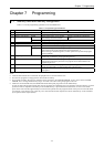
7.3 Programming Methods
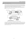
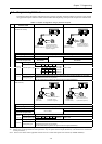
The following shows the system configuration using a personal computer and the procedures for creating a user program
using personal computer software. Please note that cables differ depending on the personal computer and software used.
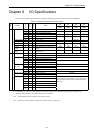
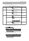
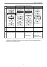
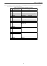
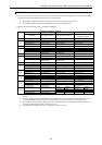
Table 7.3 System configuration using a personal computer
No.
Personal computer
software used
DOS/V PC PC9800 series personal computer
1 LADDER EDITOR
(Windows version)
DOS/V PC
(Windows
95/98/NT)
Install
LADDER EDITOR for
Windows
(HLW-PC3,
HLW-PC3E) system disks
(Japanese, English)
Install
PC9800 series PC
(Windows® 95/98/NT)
LADDER EDITOR for
Windows® (HLW-PC3)
system disks (Japanese)
CPU setting Specify H-302.
Memory assignment Specify RAM-04H (4 K memory).
Cable (MICRO-EH side) EH-RS05 EH-VCB02 EH-RS05
Cable
(personal computer side)
WVCB02H WPCB02H
10-point type There are no DIP switches (fixed to 4800 bps).
DIP SW1234
ON OFF ON OFF 38.4 kbps
ON OFF OFF OFF 19.2 kbps
OFF OFF ON OFF 9600 bps
Port 1
*1, *2
14/23/28-point type
Status
OFFOFFOFFOFF4800 bps
Same as left
10/14-point type Port 2 does not exist.
Port 2
23/28-point type
Cannot be connected with the above configuration since the RS-422/485 are used (RS-
232C/422 converters are required.)
Set the transmission speed in the special internal output (WRF03D).
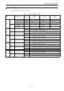
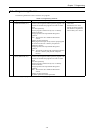
2 LADDER EDITOR
(DOS version)
D
OS/V PC
(
MS-DOS®)
Install
LADDER EDITOR DOS
version (HL-AT3E)
system disks (English)
Install
P
C9800 series
P
C (MS-DOS
®
)
LADDER EDITOR
DOS version (HL-PC3)
system disks (Japanese)
CPU setting Specify H-302.
Memory assignment Specify RAM-04H (4 k memory).
Cable (MICRO-EH side) EH-RS05
Cable
(personal computer side)
EH-VCB02
PCCB02H
10-point type There are no DIP switches (fixed to 4800 bps).
DIPSW1234
Port 1
*1, *2
14/23/28-point type
Status OFF OFF OFF OFF 4800 bps
Same as left
10/14-point type Port 2 does not exist.
Port 2
23/28-point type
Cannot be connected with the above configuration since the RS-422/485 are used (RS-
232C/422 converters are required.)
Set the transmission speed in the special internal output (WRF03D).
*1: Settings of the port 1 can be changed when the DR signal is off. When the DR signal is on, the setting is fixed.
*2: Set the port 1 to the transmission control procedure 1 by the special internal output (WRF01A). (The default is the transmission
control procedure 1.)
Note: Refer to the manual of the applicable software on how to install and operate each software (LADDER EDITOR).