


Chapter 10 PLC Installation, Mounting, Wiring
10-4
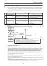
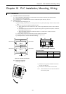
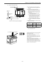
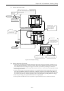
(3) Wiring to the power module
100 V AC to
240 V AC
Power supply
for the sensor
Power leakage
breaker
Shielded
insulated
transformer
Noise
filter
Figure 10.4 Power supply wiring diagram
(a) For power supply wiring, use a cable of 2
mm
2
or more to prevent a voltage drop from
occurring.
(b) For the function ground terminal (PE
terminal), use a cable of 2 mm
2
or more and
provide Class D grounding (100 Ω or less).
The appropriate length for the ground cable
is within 20 m.
1] Instrumentation panel and relay panel
grounding may be shared.
2] Avoid grounding shared with equipment
that may generate noise such as high-
frequency heating furnace, large-scaled
power panel (several kW or more),
thyristor exchanger, electric welders, etc.
3] Connect a noise filter (NF) to the power
cable.
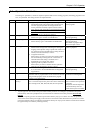
(c) Tighten the terminal screws within the torque
range as shown below.
Unit Screw
Clamping
torque
10-point M2.5 0.3 to 0.4 Nxm
14, 23, 28-point,
expansion
M3.0 0.5 to 0.6 Nxm
(d) Use the same power supply system for the
basic and expansion units.
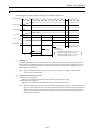
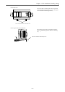
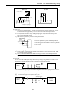
(4) Wiring cable for I/O signals
6
6
Tighten each terminal screw using a torque of the
specified torque range.
When using a crimp terminal, use one with an
outer diameter of 6 mm or less.
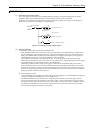
Use only up to two crimp terminals in the same
terminal. Avoid clamping down more than three
at the same time.
Only one piece of cable can be wired per
terminal if the cable type is between AWG14 and
AWG22 (cable thickness ranging between 2.1
mm
2
and 0.36 mm
2
), but two pieces can be wired
if the cable type is between AWG16 and AWG22
(between 1.3 mm
2
and 0.36 mm
2
).