


Chapter 5 Instruction Specifications
5-92
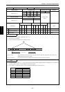
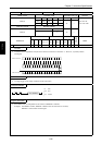
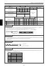
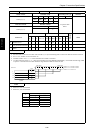
Item number Application instructions-20 Name Decode
Ladder format Condition code
Processing time (µs)
Remark
R7F4 R7F3 R7F2 R7F1 R7F0
Average Maximum
DECO (d, s, n) DER ERR SD V C
↕
zzzz
Instruction format Number of steps
Condition Steps
As per the table
below.
DECO (d, s, n) 4
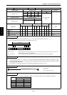
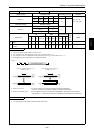
Bit Word Double word
Usable I/O
XY
R,
M
TD, SS,
CU, CT WX WY
WR,
WM TC DX DY
DR,
DM
Constant
Other
d
Decode destination head I/O
{
s Word I/O to be decoded {{{{ {
n
Number of bits to be
decoded
{
1 to 8 (decimal)
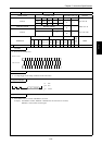
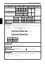
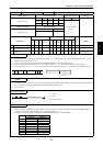
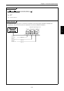
Function
• Decodes the lower n bits of s to 2
n
and outputs '1' to the decoded bits in the bit rows between d and d + 2
n
– 1 (where n = 1
to 8). Note that the value “0” is output for bits other than the decoded bits in the bit row d + 2
n
– 1.
• If n is “0,” the instruction will not be executed, and the contents of d to d + 2
n
– 1 remain unchanged.
b15 b7 b0 d+2
n
-1 d+B
1
d
2
n
s
0BH
0
00
n bits (n = 1 to 8)
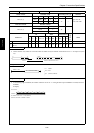
Notes
• Use this instruction so that d + 2
n
– 1 does not exceed the I/O range (R7BF and M3FFF). If it exceeds the I/O range, DER is
equal to '1' and the decoding is performed at the maximum range starting from d.
• Use 1 to 8 for n.
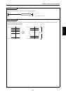
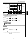
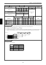
Program example
R100
LD R100
AND DIF1
[
DECO (R000, WX0000, 4)
]
DECO (R000, WX0000, 4)
DIF1
Program description
• When WX0000 = H000F, R00F, which is the 15th bit from R000 among the bits indicated by the lower four bit values of
WX0000, is set to “1” upon leading of R100.
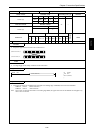
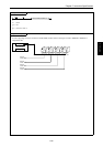
DECO (d, s, n)
Processing time (µs)
n
Average Maximum
1 105
–
2 115
–
3 195
–
4 195
–
5 317
–
6 481
–
7 829
–
8 1586
–