


Chapter 5 Instruction Specifications
5-94
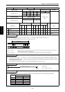
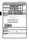
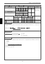
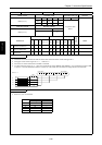
Item number Application instructions-22 Name Bit count
Ladder format Condition code
Processing time (µs)
Remark
R7F4 R7F3 R7F2 R7F1 R7F0
Average Maximum
BCU (d, s) DER ERR SD V C Upper case: W
zzzzz 33
Lower case: DW
Instruction format Number of steps
Condition Steps
BCU (d, s) Word 3 42
Double word 4
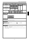
Bit Word Double word
Usable I/O
XY
R,
M
TD, SS,
CU, CT WX WY
WR,
WM TC DX DY
DR,
DM
Constant
Other
d Number of bits set to 1 {{
s
I/O that counts the bits
set to 1
{{{{{{{{
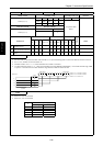
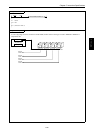
Function
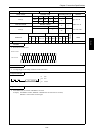
• Of the contents of s (16 bits for word and 32 bits for double word), the number of bits that are set to “1” are output to d (0 to
32).
15
5
0
0 to 32
d
1
1111 1111
15(32) 0
s
•
•
•
Number of bits that are set to "1"
•
•
••
•
•
•
•
•
•
•
•
•
•
•
•
•
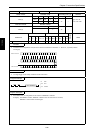
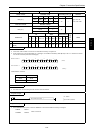
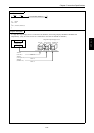
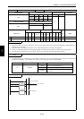
Program example
X00002
LD X00002
AND DIF2
[
BCU (WR0000, DR0020)
]
BCU (WR0000, DR0020)
DIF2
Program description
• At the leading edge of X00002, the number of bits that are set to “1” among the data input to DR0020 is counted, and set to
WR0000.
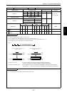
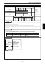
Example)
10100111000101001111000101010011
DR0020 =
A 7 1 4 F 1 5 3
the number of bits set to "1" is 16 (decimal).
Therefore, the result is WR0000 = H0010.
In the case of
BCU (d, s)