


Chapter 8 High-speed counter, PWM / Pulse train output and Analogue I/O
8-23
8.9 Analogue Input
The 23-point type CPU is equipped with two points of analogue input. The input to these two points can be set to voltage
input or current input individually. The setting of current or voltage input is made in the special internal output WRF06E.
This special internal output is stored in the FLASH memory by turning on various setting write requests (R7F6). Once it
is stored in the memory, it is not necessary to set the value again when the power is turned on for the next time.
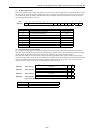
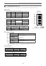
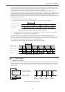
Bit:
1514131211109876543210
WRF06E:
ab Not used
Initial value:
00
Figure 8.42 Special internal output for selecting the analogue type
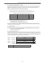
FunctionWRF06E
Setting value
Analogue CH0 (Bit a) Analogue CH1 (Bit b)
C000H Current input Current input
8000H Current input Voltage input
4000H Voltage input Current input
0000H Voltage input Voltage input
Please note that the external wiring is different for voltage input and current input. See the section regarding analogue
system wiring for the details.
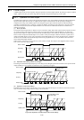
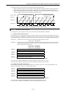
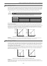
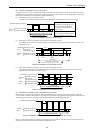
Through the above-mentioned settings, the input data of channel 0 is stored in WX 30 and the input data of channel 1 is
stored in WX31. The correspondence between analogue data and digital data is shown in the figure 8.40 (divide 0 to 10 V
and 0 to 20 mA in 0 to 4000). The voltage data is converted to 0.0025 [V] per 1H and the current data is converted to
0.005 [mA] per 1H. Therefore, the value ranges that can be measured from the output channel are 0 to 10.2375 [V] for
voltage data and 0 to 20.475 [mA] for current data, respectively.
1050
7D0H
FA0H
V
(4000)
(2000)
20100
7D0H
FA0H
mA
(4000)
(2000)
Figure 8.43 Correspondence diagrams of digital and analogue input
(Example)
If analogue input channel 0 is set to voltage input and the analogue input channel 1 is set to current input, and 3V and
14mA are applied respectively, 4B0H (1200) is stored in WX30 and AF0H (2800) is stored in WX31.
8.10 Analogue Output
The 23-point type CPU is equipped with one point of analogue output. In analogue output, digital values set at WY40 are
converted to analogue output, and then output. Switching between voltage output/current output is performed by external
wiring; analogue voltage outputs are output when connected to a voltage output terminal, and analogue current output
when connected to a current output terminal.
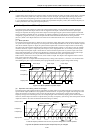
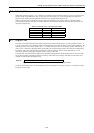
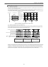
The correspondence between analogue data and digital data is shown in the figure 8.41 (divide 0 to 10 V and 0 to 20 mA
in 0 to 4000). The voltage data is converted to 0.0025 [V] per 1H and the current data is converted to 0.005 [mA] per 1H.
Therefore, the values that can be output from the output channel are 0 to 10.2375 [V] for voltage data and 0 to 20.475
[mA] for current data, respectively.
10
5
0
7D0H
(2000)
FA0H
(4000)
V
20
10
0
7D0H
(2000)
FA0H
(
4000
)
mA
Figure 8.44 Correspondence diagrams of digital and analogue output
(Example)
If 5F0H (1520) is set in WY40, 3.8 V is output from the analogue voltage output terminal. When reconnected to the
analogue current output terminal, 7.6 mA is output. Please note that if connected to both terminals by mistake, the correct
output value will not be output.