


Chapter 10 PLC Installation, Mounting, Wiring
10-8
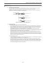
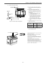
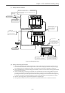
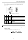
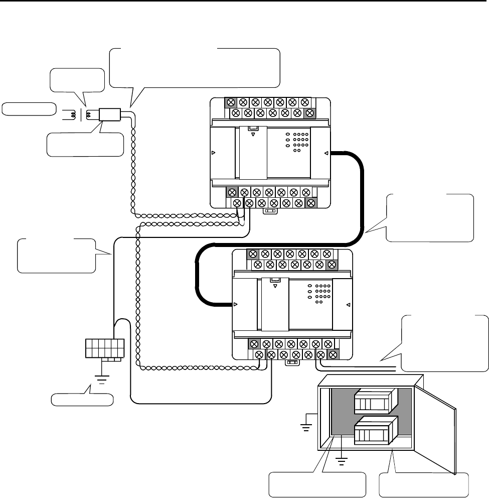
(7) Wiring to the unit terminals
NF
Wiring for the power supply
Use a 2 mm
2
cable and twist it. Leave a distance of 100
mm or more from the signal cable and 200 mm or more
from the power line.
Shield insulation
transformer
AC power supply
Connection of a noise
filter is recommended.
Use a cable 2 mm
2
or
more for the wirin
g
.
Ground wiring
Class D grounding
Leave a distance of at least
200 mm from the power
line and do not run the wire
next to the power cable.
I/O signal cable
Ex
p
ansion cable
Always segregate power
line, I/O signal and
power supply cable
Metal plate
Perform class D grounding
Outer hull (Cabinet)
Perform class D grounding
Figure 10.9 Example of wiring
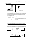
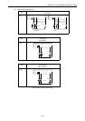
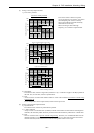
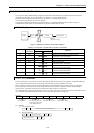
(8) Wiring to the analog I/O terminals
• Do not apply the voltage that exceeds the rated input voltage to the analog input terminals. In addition, do not
allow the current that exceeds the rated input current to flow into the analog input terminals. If a power supply
that is different from the specified power supply is connected, the product may be damaged or burned out.
•
For the channels that do not use the analog input terminals, be sure to short-circuit the analog input terminals
before using such channels.
• For the external wiring to the analog I/O terminals, use a shielded cable and make routing different from other
power lines with different voltages and signal lines. In addition, ground one end of the shield cable. However,
grounding both ends or open ends may have better effect than grounding one end of the shield cable, depending
on the noise environment in which the equipment is used. Use the appropriate grounding method accordingly.
• Place AC power supply lines, signal lines and data lines in separate pipes.
• Wire signal lines and data lines as close as possible to a grounded surface such as a cabinet and metal bar.