


EXCEL 10 W7750A,B,C CONSTANT VOLUME AHU CONTROLLER
95 74-2958—1
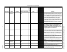
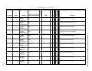
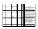
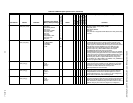
EconMtrSpd nciConfig ubEconMtrTimeS0 Seconds
20 to 240
90 P X X EconMtrTime specifies how long it takes the economizer damper motor to
travel from fully closed to fully open. This time is used to calculate the
reported position of the damper and to determine the length of over drive
time required to assure the damper is fully closed or open.
CoolMtrSpd nciConfig ubCoolMtrTimeS0 Seconds
20 to 240
90 P X X CoolMtrTime specifies how long it takes the cooling damper or valve motor
to travel from fully closed to fully open. This time is used to calculate the
reported position of the cooling damper or valve and to determine the
length of over drive time required to assure that it is fully closed or open.
HeatMtrSpd nciConfig ubHeatMtrTimeS0 Seconds
20 to 240
90 P X X HeatMtrTime specifies how long it takes the heating damper or valve motor
to travel from fully closed to fully open. This time is used to calculate the
reported position of the heating damper or valve and to determine the
length of over drive time required to assure that it is fully closed or open.
FanFailTime nciConfig ubFanFailTimeS0 Seconds
1 to 255
10 P X X Each time FAN_OUT is energized, then the node waits for FanFailTime
seconds to sample the ProofAirFlow input. If ProofAirFlow shows that the
fan is not running for FanFailTime consecutive seconds, then the control is
shut down for the minimum off time. Then the control (including the fan) is
restarted and ProofAirFlow is again tested. If ProofAirFlow shows air flow,
then the control continues to operate, but if ProofAirFlow fails to show air
flow, then the control is again shut down for the minimum off time. After
three unsuccessful restarts, a LOSS_OF_AIR_FLOW alarm is issued and
the control stays in the DISABLED mode with the FAN_OUT off.
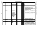
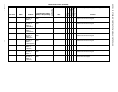
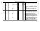
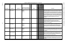
RmTempCal nciConfig siSpaceTempZeroCalS7 Degrees F
-5 to 5 (-3 to 3)
0 X X SpaceTempZeroCal provides offset calibration for the space analog sensor
input and is added to the sensed value. The range of SpaceTempZeroCal
is between -5 and 5 degrees F.
TempOffstCal1 nciConfig siResistiveOffsetCalS7[0] Degrees F
-15 to 15 (-9 to 9)
0 ResistiveOffsetCal[0] provides offset calibration for the resistive analog
sensor input and is added to the sensed value. The range of
ResistiveOffsetCal[0] is between -15 and 15 degrees F.
TempOffstCal2 nciConfig siResistiveOffsetCalS7[1] Degrees F
-15 to 15 (-9 to 9)
0 ResistiveOffsetCal[1] provides offset calibration for the resistive analog
sensor input and is added to the sensed value. The range of
ResistiveOffsetCal[1] is between -15 and 15 degrees F.
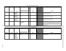
VoltOffstCal1 nciConfig siVoltageOffsetCalS12[0] volts
-1 to 1
0 VoltageOffsetCal[0] provides offset calibration for the voltage/current
analog sensor input and is added to the sensed value. The current analog
sensor is converted to a voltage by a 249 ohm resister wired across the
input terminals. The range of VoltageOffsetCal[0] is between -1 and 1 volt.
Voltage offsets are new in engineering units (not volts).
VoltOffstCal2 nciConfig siVoltageOffsetCalS12[1] volts
-1 to 1
0 VoltageOffsetCal[1] provides offset calibration for the voltage/current
analog sensor input and is added to the sensed value. The current analog
sensor is converted to a voltage by a 249 ohm resister wired across the
input terminals. The range of VoltageOffsetCal[1] is between -1 and 1 volt.
Voltage offsets are new in engineering units (not volts).
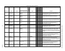
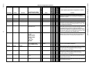
FanOnHtMode nciConfig FanOnHeat FALSE
TRUE
0
1
TRUE P X X FanOnHeat specifies the operation of the fan during HEAT mode. If
FanOnHeat is 1(TRUE), then the fan is on when the mode is HEAT. If
FanOnHeat is a 0 (FALSE) the fan is never turned on when the mode is
HEAT, and typically a thermostatically controlled switch sensing heated air
temperature turns on the fan.
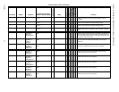
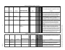
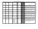
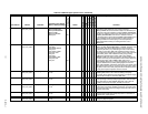
Table 25. Configuration Parameters. (Continued)
User Address NvName Field Name
Engineering Units: English
(Metric) or States plus Range
Digital State or
Value of State
Default
E-Vision (M, P, S)
Share
Map
Direct Access
Hardware Config.
Manual Config.
Test
E-Vision Legend: (M) Monitor, (P) Parameter, (S) Schematic
NOTE: Physical I/O points that are configurable are in Table 20.
Comments