


EXCEL 10 W7750A,B,C CONSTANT VOLUME AHU CONTROLLER
3 74-2958—1
List of Figures
Fi
g
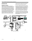
. 1. T
y
pical s
y
stem overview. ................................................................................................................................................ 6
Fi
g
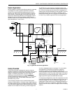
. 2. T
y
pical W7750 control application. ................................................................................................................................. 7
Fi
g
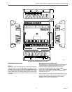
. 3. Excel 10 W7750A Constant Volume AHU Controller. ..................................................................................................... 12
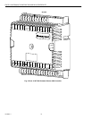
Fi
g
. 4. W7750A construction in in.
(
mm
)
. ................................................................................................................................... 13
Fi
g
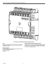
. 5. Excel 10 W7750B Constant Volume AHU Controller. ..................................................................................................... 14
Fi
g
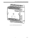
. 6. Excel 10 W7750C Constant Volume AHU Controller. .................................................................................................... 15
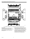
Fi
g
. 7. W7750B,C construction in in.
(
mm
)
. W7750C
(
shown
)
has three 4 to 20 mA analo
g
outputs.
)
..................................... 16
Fi
g
. 8. DIN rail adapters. ............................................................................................................................................................ 17
Fi
g
. 9. Functional profile of L
ON
M
ARK
® RTU ob
j
ect details
(
variables not implemented in Excel 10 CVAHU
are
g
re
y
ed
)
........................................................................................................................................................................ 18
Fi
g
. 10. T7770A,B,C,D construction in in.
(
mm
)
. ....................................................................................................................... 20
Fi
g
. 11. T7560A,B construction in in.
(
mm
)
. ............................................................................................................................... 21
Fi
g
. 12. C7770A construction in in.
(
mm
)
. .................................................................................................................................. 21
Fi
g
. 13. Fan with two sta
g
es of heatin
g
and two sta
g
es
of coolin
g
........................................................................................................................................................................... 24
Fi
g
. 14. Fan, modulatin
g
heatin
g
and modulatin
g
coolin
g
. ......................................................................................................... 24
Fi
g
. 15. Heat pump with two compressors and auxiliar
y
heat sta
g
e
(
s
)
....................................................................................... 25
Fi
g
. 16. Economizer control. ...................................................................................................................................................... 25
Fi
g
. 17. Modulatin
g
heat with pneumatic valve actuator............................................................................................................. 26
Fi
g
. 18. Connectin
g
the portable operator terminal
to the L
ON
W
ORKS
® Bus..................................................................................................................................................... 29
Fi
g
. 19. Wirin
g
la
y
out for one doubl
y
terminated dais
y
-chain L
ON
W
ORKS
® Bus se
g
ment. ........................................................ 31
Fi
g
. 20. Wirin
g
la
y
out for two sin
g
l
y
terminated L
ON
W
ORKS
® Bus se
g
ments............................................................................. 32
Fi
g
. 21. NEMA class 2 transformer volta
g
e output limits............................................................................................................ 34
Fi
g
. 22. Power wirin
g
details for one Excel 10 per transformer. ................................................................................................. 34
Fi
g
. 23. Power wirin
g
details for two or more Excel 10s per transformer. .................................................................................. 34
Fi
g
. 24. Transformer power wirin
g
details for one Excel 10 used in UL 1995 e
q
uipment
(
U.S. onl
y)
......................................... 35
Fi
g
. 25. Attachin
g
two or more wires at terminal blocks.............................................................................................................. 36
Fi
g
. 26. W7750B Hi
g
h-Side/Low-Side selectable switchin
g
and
j
umper location....................................................................... 36
Fi
g
. 27. T
y
pical W7750A Controller AHU application wirin
g
dia
g
ram.
(
For more information on note 2,
refer to Fi
g
. 25.
)
................................................................................................................................................................ 38
Fi
g
. 28. T
y
pical W7750A Controller with separate transformer application wirin
g
dia
g
ram.
(
For more information on note 2, refer to Fi
g
. 25.
)
............................................................................................................ 38
Fi
g
. 29. W7750A Controller floatin
g
economizer damper wirin
g
dia
g
ram.
(
For more information on note 2, refer to Fi
g
. 25.
)
... 39
Fi
g
. 30. T
y
pical W7750B Controller with sta
g
ed heatin
g
and coolin
g
wirin
g
dia
g
ram.
(
For more information on note 2, refer to Fi
g
.
25.
)
.................................................................................................................................................................................... 40
Fi
g
. 31. W7750B Controller with floatin
g
heatin
g
, coolin
g
and economizer wirin
g
dia
g
ram.
(
For more information on note 2, refer
to Fi
g
. 25.
)
......................................................................................................................................................................... 40
Fi
g
. 32. W7750B,C Controller PWM damper actuator wirin
g
dia
g
ram.
(
For more information on note 2, refer to
Fi
g
. 25.
)
............................................................................................................................................................................. 41
Fi
g
. 33. W7750B,C wirin
g
dia
g
ram with 4 to 20 mA enthalp
y
sensors and di
g
ital inputs.
(
For more information on note 2, refer to
Fi
g
. 25.
)
............................................................................................................................................................................. 41
Fi
g
. 34. W7750B,C wirin
g
dia
g
ram with C7600C 4 to 20 mA solid state humidit
y
sensor.
(
For more information on note 2, refer to
Fi
g
. 25.
)
............................................................................................................................................................................. 42
Fi
g
. 35. W7750C Controller with 4-to-20 mA heatin
g
, coolin
g
and economizer wirin
g
dia
g
ram. AOs must use terminals 16, 17 or
18. The AOs can be set to be reverse actin
g
.
(
For more information on note 2, refer to Fi
g
. 25.
)
.................................... 42
Fi
g
. 36. Pneumatic transducer to W7750B,C
(
B shown, see trian
g
le note 4
)
. ......................................................................................................................................... 43
Fi
g
. 37. RP7517,B pneumatic transducer to W7750C................................................................................................................ 43
Fi
g
. 38. T
y
pical doubl
y
terminated dais
y
-chain L
ON
W
ORKS
® Bus se
g
ment termination module wirin
g
dia
g
ram. ..................... 44
Fi
g
. 39. L
ON
W
ORKS
® Bus termination wirin
g
options. ............................................................................................................... 45
Fi
g
. 40. Temperature sensor resistance plots............................................................................................................................. 49
Fi
g
. 41. Location of the Service Pin Button................................................................................................................................. 50
Fi
g
. 42. LED location on W7750................................................................................................................................................. 51
Fi
g
. 43. The T7770C,D Wall Modules LED and B
y
pass pushbutton locations........................................................................... 51
Fi
g
. 44. The T7560A,B Di
g
ital Wall Module B
y
pass pushbutton location................................................................................... 51
Fi
g
. 45. LED and B
y
pass pushbutton operation. ....................................................................................................................... 56
Fi
g
. 46. Setpoint rampin
g
parameters with ramp rate calculation............................................................................................... 57
Fi
g
. 47. Setpoint rampin
g
parameters with setpoint calculation.................................................................................................. 58