


EXCEL 10 W7750A,B,C CONSTANT VOLUME AHU CONTROLLER
61 74-2958—1
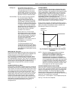
coolin
g
control al
g
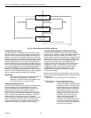
orithm compares the current space
temperature to the EffectiveHeatSetPt, and calculates a PID
error si
g
nal. This error si
g
nal causes the heatin
g
sta
g
e
outputs to be c
y
cled, as re
q
uired, to drive the space
temperature back to the Setpoint. Fi
g
. 50 illustrates the
relationship between PID error and sta
g
ed output activit
y
.
As the error si
g
nal increases, the space temperature
g
ets
further awa
y
from the setpoint, or is remainin
g
below the
setpoint as time elapses, additional sta
g
es of heatin
g
are
ener
g
ized until, if PID error reaches 100 percent, all
confi
g
ured sta
g
es are on.
The PID control al
g
orithm used to control sta
g
ed heatin
g
is
anticipator-driven, and is similar to the al
g
orithm used in the
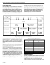
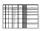
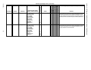
T7300 commercial thermostat. All sta
g
in
g
events are sub
j
ect
to a minimum intersta
g
e time dela
y
, that is based on the
c
y
cles per hour user settin
g
(
HeatC
y
cHr
)
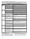
. The minimum
intersta
g
e time dela
y
ran
g
es from 90 seconds
(
at 12 c
y
cles
per hour
)
to ei
g
ht minutes
(
at two c
y
cles per hour
)
. See Table
17. The user has the option to disable the minimum run timer
for heatin
g
(
DisMinHtTimer
)
. If the minimum run timer is
disabled, the intersta
g
e time dela
y
is fixed at 20 seconds. The
c
y
clin
g
rate is separatel
y
selectable for heatin
g
and coolin
g
between two and 12 c
y
cles per hour
(
cph
)
.
Setpoints for the PID
g
ains allow for unit-b
y
-unit ad
j
ustment of
the control loop, if re
q
uired; however, an
y
chan
g
e from the
default values should be minimal.
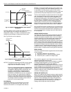
CASCADE CONTROL OF MODULATING COOLING/HEATING
The Excel 10 W7750 Controller supports modulatin
g
coolin
g
and heatin
g
valves. These valves can be controlled directl
y
from the space temperature
(
like the sta
g
ed control
)
or, if the
CascCtrl fla
g
is set, the
y
are modulated to maintain the
dischar
g
e air temperature at its setpoint. The dischar
g
e air
setpoint is calculated based on the space temperature
deviation from the space setpoint. This is commonl
y
called
cascade control. In the W7750 Controller, cascade control is
available for use with PWM
(
W7750B,C onl
y)
and Series 60
modulatin
g
heatin
g
and coolin
g
, but not for use with sta
g
ed
heatin
g
/coolin
g
.
Setpoints for the PID
g
ains and for the control band allow for
unit-b
y
-unit ad
j
ustment of the control loops, if re
q
uired;
however, an
y
chan
g
e from the default values should be
minimal. Also, the W7750 Controller uses an adaptive
al
g
orithm
(
patent pendin
g)
to continuousl
y
assess the validit
y
of the calculated dischar
g
e setpoint, and ad
j
ust it, as needed,
to ensure precise, accurate control.
SERIES 60 MODULATING CONTROL
Series 60 Control is also commonl
y
referred to as Floatin
g
Control. The Excel 10 W7750A,B,C Controllers can drive
Series 60 t
y
pe actuators to control a modulatin
g
coolin
g
valve,
a heatin
g
valve, and economizer dampers. When floatin
g
control is used, the full-stroke motor drive time of the actuator
must be entered into the confi
g
uration parameter CoolMtrSpd
(
for coolin
g)
, HeatMtrSpd
(
for heatin
g)
, or EconMtrSpd
(
for the
economizer dampers
)
.
PULSE WIDTH MODULATING (PWM) CONTROL
The Excel 10 W7750B,C Controllers can drive a PWM-t
y
pe
actuator to control a modulatin
g
coolin
g
valve, a heatin
g
valve, and economizer dampers. PWM control positions the
actuator based on the len
g
th, in seconds, of the pulse from
the di
g
ital output. The controller outputs a pulse whose len
g
th
consists of two parts, a minimum and a maximum. The
minimum pulse time represents the analo
g
value of zero
percent
(
also indicates a si
g
nal presence
)
and the maximum
pulse len
g
th that represents an analo
g
value of 100 percent. If
the analo
g
value is
g
reater than zero percent, an additional
time is added to the minimum pulse time. The len
g
th of time
added is directl
y
proportional to the ma
g
nitude of the analo
g
value. If PWM control is used, the confi
g
uration parameters
for the PWM operation must be specified. These are
PwmPeriod, PwmZeroScale, and PwmFullScale. These three
parameters are shared b
y
all confi
g
ured PWM outputs; this
means the heatin
g
, coolin
g
, and economizer actuators must
be confi
g
ured to accept the same st
y
le of PWM si
g
nal.
Example
: To find the pulse width of a valve actuator
(
for
example stroke mid position - 50 percent
)
with the
PwmZeroScale = 0.1 seconds, PwmFullScale = 25.5
seconds, and the PwmPeriod = 25.6 seconds. There are 256
increments available, so the number of increments re
q
uired
for 50 percent would be
(
0.5 X 256
)
or 128. The time for each
increment for this industr
y
standard pulse time is 0.1 seconds.
The pulse width is the minimum time
(
0.1 second
)
+ the
number of increments
(
128 times the
(
0.1 second
)
plus 0. 1
)
=
12.9 seconds. The W7750B,C Controllers would command
the valve output on for 12.9 seconds for the PwmPeriod of
25.6 seconds to maintain the valve position at 50 percent.
OUTDOOR AIR LOCKOUT OF HEATING/COOLING
A mechanism is provided in the W7750 to disable the heatin
g
e
q
uipment if the outdoor air temperature rises above the
OaTempHtLkOut setpoint. Similarl
y
, the coolin
g
e
q
uipment is
disabled if the outdoor air temperature falls below the
OaTempClLkOut setpoint. The al
g
orithm supplies a fixed 2
°
F
(
1.1
°
C
)
h
y
steresis with the lock-out control to prevent short
c
y
clin
g
of the e
q
uipment.
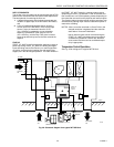
ECONOMIZER DAMPER CONTROL
A mixed-air economizer damper packa
g
e can be controlled to
assist mechanical coolin
g
in maintainin
g
the dischar
g
e air at
setpoint. Therefore, if modulatin
g
economizer damper control
is desired, a dischar
g
e air temperature sensor is re
q
uired. If
the outdoor air is not currentl
y
suitable for coolin
g
use
(
see the
Economizer Enable/Disable Control section
)
, the outdoor air
damper is held at the user-settable minimum position
(
EconMinPos
)
for ventilation purposes.
Because the outdoor air can be used to supplement
mechanical coolin
g
, the economizer operates as if it were the
first sta
g
e of coolin
g
. So, if the outdoor air is suitable for
coolin
g
use, the mechanical coolin
g
(
either sta
g
ed or
modulatin
g)
is held off until the economizer has reached its
full
y
open position. Then, if the dischar
g
e temperature
continues to be above setpoint, the mechanical coolin
g
is
allowed to come on. If the outdoor air is
not
suitable for
coolin
g
use, the economizer is set to its minimum position,
and mechanical coolin
g
is allowed to come on immediatel
y
.
When the controller is in the Heat mode, the economizer is
held at the minimum position settin
g
(
EconMinPos
)
. The
minimum position settin
g
is onl
y
used durin
g
Occupied mode
operation. When in Standb
y
or Unoccupied modes, the
outdoor air dampers are allowed to full
y
close if there is no call
for coolin
g
, or if the outside air is not suitable for coolin
g
use.