


EXCEL 10 W7750A,B,C CONSTANT VOLUME AHU CONTROLLER
74-2958—124
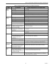
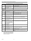
Allowable Heating and Cooling Equipment
Configurations
Each W7750 device can control a variet
y
of different t
y
pes of
mechanical coolin
g
and heatin
g
e
q
uipment within roof top air
handlers. See Fi
g
. 13 throu
g
h 17 for a conceptual overview of
some t
y
pical confi
g
urations. For specific wirin
g
details, see
the Prepare Wirin
g
Dia
g
rams section.
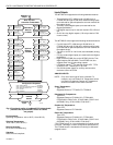
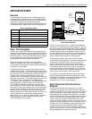
STAGED HEATING/COOLING CONTROL
Sta
g
ed e
q
uipment control is available for up to four sta
g
es of
heatin
g
or four sta
g
es of coolin
g
. On the W7750, the sta
g
es
are activated throu
g
h di
g
ital outputs
(
Triacs on the W7750B,C
and dr
y
-contact rela
y
s on the W7750A
)
one for each sta
g
e
wired to 24 Vac contactors
(
see Fi
g
. 27 and 30 in Step 4.
Prepare Wirin
g
Dia
g
rams section for wirin
g
details
)
. Note that
the number of ph
y
sical Di
g
ital Outputs
(
DOs
)
on the controller
limits the total number of sta
g
es that can be controlled. For
example, the W7750A Model has six di
g
ital outputs, and
because one is used for the suppl
y
fan, there are five DOs
available for an
y
combination of heatin
g
and coolin
g
sta
g
es
(
with a maximum of four sta
g
es of heatin
g
and four sta
g
es for
coolin
g)
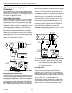
. The W7750B Model offers two additional DOs, for a
total of ei
g
ht. The W7750C offers five DOs and three Analo
g
Outputs
(
AOs
)
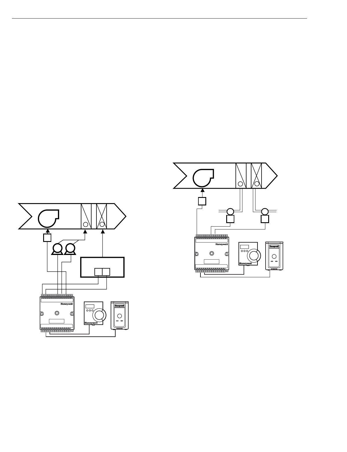
. Fi
g
. 13 shows a t
y
pical application of two
sta
g
es of heat and two sta
g
es of coolin
g
.
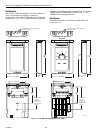
Fig. 13. Fan with two stages of heating and two stages
of cooling.
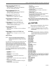
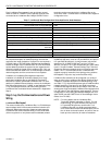
MODULATING HEATING/COOLING CONTROL
The W7750 Controller provides modulatin
g
e
q
uipment control
for heatin
g
and coolin
g
e
q
uipment
(
and economizer dampers,
see Fi
g
. 16
)
usin
g
either Series 60 Floatin
g
Control or Pulse
Width Modulated
(
PWM
)
control,
(
PWM control is available on
the W7750B,C
only
)
. The Series 60 Modulatin
g
Control is
provided throu
g
h two Rela
y
di
g
ital outputs on the W7750A or
two Triac di
g
ital outputs on the W7750B,C
(
one to pulse the
valve actuator open and one to pulse it closed
)
. PWM control
positions the actuator based on the len
g
th, in seconds, of the
pulse from the di
g
ital output. For PWM, the controller outputs
a pulse whose len
g
th consists of two parts, a minimum and a
maximum. The minimum pulse time represents the analo
g
value of 0 percent and the maximum pulse len
g
th that
represents an analo
g
value of 100 percent. If the analo
g
value
is
g
reater than 0 percent, an additional time is added to the
minimum pulse time. The len
g
th of time added is directl
y
proportional to the ma
g
nitude of the analo
g
value. The PWM
actuator will be
g
in to use the analo
g
value at the end of the
pulse and will continue to use this value until a new pulse is
received. Refer to Appendix B under PWM Control for an
example. Series 60 actuators are
g
enerall
y
less expensive
than those for PWM, but the trade-off is that PWM re
q
uires
onl
y
a sin
g
le controller di
g
ital output while floatin
g
control
uses two DOs. Refer to Appendix B under Series 60
Modulatin
g
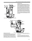
Control for an example. Fi
g
. 14 illustrates a
s
y
stem with modulatin
g
heatin
g
and coolin
g
(
see Fi
g
. 29 and
31 in Step 4. Prepare Wirin
g
Dia
g
rams section.
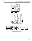
Fig. 14. Fan, modulating heating and modulating cooling.
NOTE: Pneumaticall
y
actuated valves can be controlled
usin
g
a pneumatic transducer device. See Fi
g
. 17.
Also, transducer devices are available from third
part
y
vendors to convert PWM outputs to a volta
g
e
or current si
g
nal if desired.
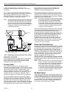
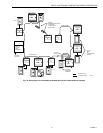
HEAT PUMP CONTROL
The W7750 Controller handles heat pump applications
similarl
y
to sta
g
ed heatin
g
/coolin
g
control. Heat pump
applications are supported b
y
providin
g
outputs for up to four
compressor sta
g
es, a chan
g
e-over rela
y
for the refri
g
erant
reversin
g
valve, and up to four sta
g
es of auxiliar
y
heat. Note
that the W7750A Model has six di
g
ital outputs, and therefore,
with one DO used for the suppl
y
fan and one for the chan
g
e-
over rela
y
, there are four outputs available for an
y
combination of compressors and auxiliar
y
heat sta
g
es. The
W7750B Model offers two additional DOs for a total of ei
g
ht,
while the W7750C Model offers five DOs and 3 AOs. Fi
g
. 15
illustrates a t
y
pical heat pump s
y
stem with auxiliar
y
heat.
M17491
MIXED
AIR
HEAT
COIL
COOL
COIL
DISCHARGE
AIR
W1
W2
Y1 Y2
-
+
FAN
FAN
STARTER
COMPRESSORS
GAS COMBUSTION
CONTROLS
EXCEL 10
CVAHU
W7750A,B,C
T7560A,B OR T7770
MIXED
AIR
HEAT
COIL
COOL
COIL
DISCHARGE
AIR
-
+
FAN
FAN
STARTER
CHILLED
WATER
VALVE
HOT
WATER
VALVE
M17492
EXCEL 10
CVAHU
W7750A,B,C
T7560A,B OR T7770