


EXCEL 10 W7750A,B,C CONSTANT VOLUME AHU CONTROLLER
74-2958—154
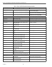
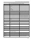
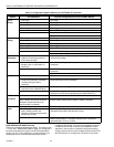
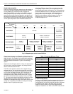
Table 15. Configuration Options Summary For W7750A,B,C Controllers.
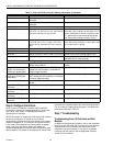
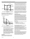
ROOM TEMPERATURE SENSOR (RmTemp)
This is the room space temperature sensor. This sensor is the
T7770 or the T7560A,B Wall Module. When it is confi
g
ured, it
provides the temperature input for the W7750 temperature
control loop. If it is not confi
g
ured, it is re
q
uired that a room
temperature sensor value be transmitted from another
L
ON
W
ORKS
Bus device. If no valid room temperature value is
available to the W7750 Controller, the temperature control
al
g
orithm in the controller is disabled, causin
g
the heatin
g
,
coolin
g
, and economizer control outputs to be turned off. If the
W7750 Controller is confi
g
ured for Continuous Fan
(
rather
Option
Possible Configurations for the
W7750A Model Possible Configurations for the W7750B,C Models
Type of
1. One sta
g
e. 1. One sta
g
e.
Heating
2. Two sta
g
es. 2. Two sta
g
es.
3. Three sta
g
es. 3. Three sta
g
es.
4. Four sta
g
es. 4. Four sta
g
es.
5. None. 5. Series 60 Modulatin
g
electric valve, or pneumatic via transducer.
6. Pulse Width Modulatin
g
electric valve, or pneumatic via transducer.
7. None.
Type of
1. One sta
g
e. 1. One sta
g
e.
Cooling
2. Two sta
g
es. 2. Two sta
g
es.
3. Three sta
g
es. 3. Three sta
g
es.
4. Four sta
g
es. 4. Four sta
g
es.
5. None. 5. Series 60 Modulatin
g
electric valve, or pneumatic via transducer.
6. Pulse Width Modulatin
g
electric valve, or pneumatic via transducer.
7. None.
Type of
Economizer
1. Di
g
ital Output Enable/Disable
si
g
nal for controllin
g
an external
economizer packa
g
e.
1. Di
g
ital Output Enable/Disable si
g
nal for controllin
g
an external
economizer packa
g
e.
2. Series 60 Modulatin
g
electric
damper motor, or pneumatic via
transducer.
2. Series 60 Modulatin
g
electric damper motor, or pneumatic via
transducer.
3. None. 3. Pulse Width Modulatin
g
electric damper motor, or pneumatic via
transducer.
4. None.
IAQ Option
1. None. 1. None.
2. Local IAQ Di
g
ital Input—directl
y
wired to the controller.
(
Contacts
closed means poor IAQ is
detected.
)
2. Local IAQ Di
g
ital Input—directl
y
wired to the controller.
(
Contacts
closed means poor IAQ is detected.
)
3. Network
(
IAQ Override si
g
nal
received via the L
ON
W
ORKS
Bus
)
.
3. Network
(
IAQ Override si
g
nal received via the L
ON
W
ORKS
Bus
)
.
4. Local CO
2
Analo
g
Input—directl
y
wired to the controller.
(
The sensor
must be a 0 to 10V device representin
g
0 to 2000 PPM CO
2
.
)
Coil Freeze
1. None. 1. None.
Stat Option
2. Local Coil Freeze Stat Di
g
ital
Input—directl
y
wired to the controller.
(
Contacts closed means that coil
freeze condition is sensed.
)
2. Local Coil Freeze Stat Di
g
ital Input—directl
y
wired to the controller.
(
Contacts closed means that coil freeze condition is sensed.
)
Filter Monitor
1. None. 1. None.
Option
2. Local Dirt
y
Filter Di
g
ital
Input—directl
y
wired to the
controller.
(
Contacts closed means
that the filter is dirt
y
.
)
2. Local Dirt
y
Filter Di
g
ital Input—directl
y
wired to the controller.
(
Contacts closed means that the filter is dirt
y
.
)
3. Local Analo
g
Input for Differential Pressure across the Filter
(
directl
y
wired to the controller
)
. The sensor must be a 2 to 10V device
representin
g
0 to 5 inw
(
1.25 kPa
)
.