


EXCEL 10 W7750A,B,C CONSTANT VOLUME AHU CONTROLLER
73 74-2958—1
WindowSw nvoIO WindowOpen FALSE
TRUE
0
1
FALSE M,
S
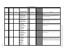
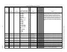
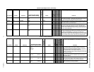
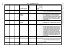
WindowOpen is the state of the digital input configured and wired to a
window open sensor switch. 1 (input open circuit) means that the window is
open, and 0 (input shorted) means that the window is closed.
MonitorSw nvoIO MonSwitch FALSE
TRUE
0
1
FALSE MonSwitch is the state of the digital input configured and wired to a general
purpose monitor switch. 1 (input shorted) means that switch is closed, and
0 (input open) means that the switch is open.
ModelSw nvoIO Model FALSE
TRUE
0
1
FALSE X Model indicates the Model of the node. One of the digital inputs is
connected to a printed wiring board trace to let the embedded software
know what kind of hardware is present. If Model is 1 (input held high), the
hardware is the W7750B Model. If Model is 0 (input shorted to ground), the
hardware is the W7750A Model.
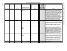
nvoIO SchedMaster FALSE
TRUE
0
1
FALSE M X If ScheduleMaster is 1 (input shorted), the node is the schedule master and
the locally connected time clock will be sent via TimeClk to other nodes on
the network. If ScheduleMaster is 0, (input open), the node is not a
schedule master and nvoTimeClk will not be sent on the network even if the
time clock input is configured. If the ScheduleMaster input is not configured
by Select, TimeClk reports the state of the locally connected time clock.
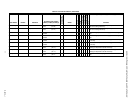
Table 20. Input/Output Points. (Continued)
User Address NvName Field Name
Engineering Units: English
(Metric) or States plus Range
Digital State or
Value of State
Default
E-Vision (M, P, S)
Share
Map
Direct Access
Hardware Config.
Manual Config.
Test
E-Vision Legend: (M) Monitor, (P) Parameter, (S) Schematic
Comments
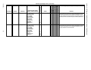
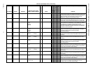
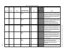
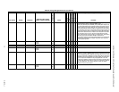
Table 21. Control Parameters.
User Address NvName Field Name
Engineering Units: English
(Metric) or States plus Range
Digital State or
Value of State
Default
E-Vision (M, P, S)
Share
Map
Direct Access
Hardware Config.
Manual Config.
Test
E-Vision Legend: (M) Monitor, (P) Parameter, (S) Schematic
Comments
DaTempLoLim nciAux1SetPt siLowLimitDischAirTempS7 Degrees F
0 to 60
Degrees C
(-1 to 16)
45 P X X When the discharge air temperature falls below
LowLimitDischAirTemp, the outdoor air dampers are closed to a
position that corrects the low temperature problem. If mechanical
cooling is active when the discharge air falls below
LowLimitDischAirTemp, the mechanical cooling cycles off after the
minimum run times are obeyed to allow the dampers to return open
and provide free cooling.
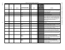
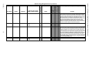
DaTempHiLim nciAux1SetPt siMaxDisAirTempHeatS7 Degrees F Degrees C
65 to 135 (18 to 57)
100 P X X When the mode is HEAT, and the CascadeControl is enabled, the
discharge air temperature is controlled to a value not to exceed
MaxDisAirTempHeat.
DlcBumpTemp nciAux1SetPt siDlcBumpTempS7 Degrees F Degrees C
0 to +10 (-18 to -12)
3 P X X When DlcShed is not 0 then the setpoint is shifted by DlcBumpTemp
in the energy saving direction. When DlcShed changes from 1 to 0,
the setpoint shift ramps back to 0 over a 30 minute interval.
OaTempHtLkOut nciAux1SetPt ubOdHtLockOutTempS0 Degrees F Degrees C
0 to 90 (-18 to 32)
70 P X X When the outdoor air temperature is greater than
OdHtLockOutTemp, the heating is disabled.