


EXCEL 10 W7750A,B,C CONSTANT VOLUME AHU CONTROLLER
35 74-2958—1
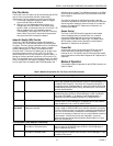
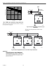
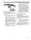
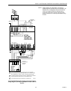
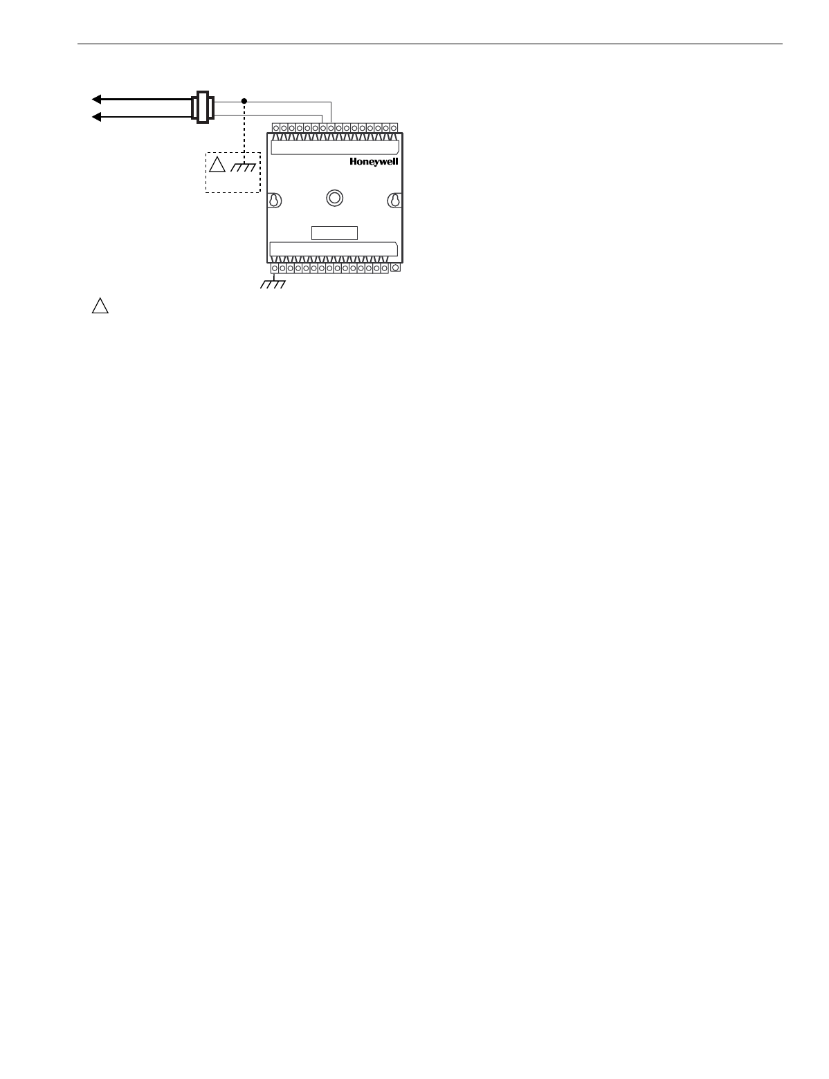
Fig. 24. Transformer power wiring details for one Excel 10
used in UL 1995 equipment (U.S. only).
IMPORTANT
Notes on power wiring:
• All field wiring must conform to local codes and ordi-
nances or as specified on installation wiring dia-
grams.
• To maintain NEC Class 2 and UL ratings, the instal-
lation must use transformers of 100 VA or less
capacity.
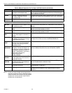
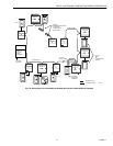
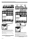
• For multiple controllers operating from a single trans-
former, the same side of the transformer secondary
must be connected to the same input terminal in
each controller (21 on the W7750A and 24 on the
W7750B,C) and the ground terminals must be con-
nected to a verified earth ground for each controller
in the group. See Fig. 23. (Controller configurations
are not necessarily limited to three devices per trans-
former.)
• For the W7750B,C Controller (which has Triac out-
puts), all output devices must be powered from the
same transformer as the one powering the Excel 10
W7750 Controller.
• Use the heaviest gauge wire available, up to 14
AWG (2.0 mm
2
) with a minimum of 18 AWG (1.0
mm
2
) for all power and earth ground connections.
• To minimize EMI noise, do not run Triac output wires
in the same conduit as the input wires or the L
ON
-
W
ORKS
Bus communications wiring.
• Unswitched 24 Vac power wiring can be run in the
same conduit as the L
ON
W
ORKS
Bus cable.
• Make earth ground connections with the shortest
possible wire run using 14 AWG (2.0 mm
2
) wire. A
good earth ground is essential for W7750 operation.
Ideally, connect the earth ground to the ground bus
at a motor control center or circuit breaker panel.
However, if the nearest ideal earth ground is inac-
cessible, consider an alternate source for earth
ground. Metal water pipe is generally a good ground,
but do not use sprinkler pipe if prohibited by local
codes. Attention must be given when duct work, con-
duit, or rebar are to be considered as ground
sources. It is the responsibility of the installer to
assure that these structures are tied back to a known
earth ground.
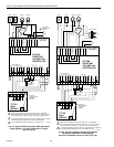
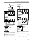
Step 4. Prepare Wiring Diagrams
General Considerations
The purpose of this step is to assist the application en
g
ineer in
developin
g
j
ob drawin
g
s to meet
j
ob specifications. Wirin
g
details are included for the W7750A,B,C Controllers and the
T7770 and T7560A,B Wall Modules. The drawin
g
s detail I/O,
power, and L
ON
W
ORKS
Bus communication wirin
g
connections.
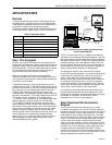
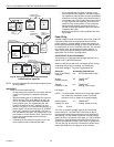
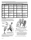
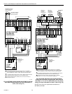
NOTE: For field wirin
g
, when two or more wires, other than
14 AWG
(
2.0 mm
2
)
are to be attached to the same
connector block terminal, be sure to twist them
to
g
ether. Deviation from this rule can result in
improper electrical contact. See Fi
g
. 25.
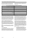
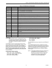
The connector block terminals on the W7750 Controllers and
on the T7770 Wall Modules accept 14 throu
g
h 22 AWG
(
2.0 to
0.34 mm
2
)
wire. The connector block terminals on the
T7560A,B Wall Modules accept 18 throu
g
h 22 AWG
(
1.0 to
0.34 mm
2
)
wire. Table 9 lists wirin
g
t
y
pes, sizes, and len
g
th
restrictions for Excel 10 products.
M10088A
24 VAC
LINE VOLTAGE
GREATER
THAN 150 VAC
TRANSFORMER
W7750
EARTH
GROUND
EARTH
GROUND
IF THE W7750 CONTROLLER IS USED IN UL 1995 EQUIPMENT AND THE
PRIMARY POWER IS MORE THAN 150 VOLTS, GROUND 24 VAC COM
SIDE OF TRANSFORMER SECONDARY.
1
1
1