


EXCEL 10 W7750A,B,C CONSTANT VOLUME AHU CONTROLLER
74-2958—176
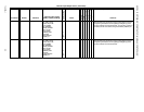
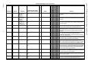
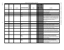
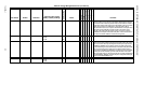
OaEnthEn nciAux1SetPt ubOdEnthalpyEnableS2 btu/lb
0 to 65
25 P X X If Config.EconEnable is SINGLE_ENTH, and calculated outdoor
enthalpy is less than OdEnthalpyEnable, and outdoor temperature is
less than OdEconEnableTemp, then outdoor air is judged suitable to
augment mechanical cooling.
EconMinPos nciAux1SetPt ubEconMinPosS0 Percentage
0 to 100
0 P X X The minimum allowed position of the economizer damper for HEAT
and COOL is EconMinPos.
EconIAQPos nciAux1SetPt ubEconIaqPosS0 Percentage
0 to 100
80 P X X The control overrides the economizer damper to EconIaqPos when
poor indoor air quality is detected.
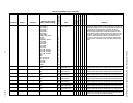
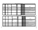
IAQSetpt nciAux1SetPt siCO2IaqLimitS0 PPM
0 to 2000
800 P X X When an analog CO2 sensor is configured and the sensed CO2 is
greater than CO2IaqLimit, then poor indoor air quality is detected
and Data1.OverRide is set to 1. When the sensed CO2 is less than
CO2IaqLimit, then the indoor air quality is considered acceptable
and Data1.IaqOverRide is set to 0. oData1.IaqOverRide is used to
set the economizer damper to Aux1SetPt. EconIaqPos and to
possibly turn on the heat according to the state of
Config.IaqUseHeat.
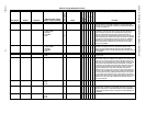
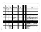
PwmPeriod nciAux1SetPt siPwmPeriodS4 100 P X X When pulse width modulation is used, the period of one pulse width
modulation cycle is PwmPeriod seconds. The smallest resolution is
0.1 seconds.
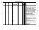
PwmZeroScale nciAux1SetPt siPwm0pcntS4 Seconds
0 to 2047
1 P X X When pulse width modulation is used, the period of a pulse for zero
percent output (damper or valve at open position) is Pwm0pcntS4
seconds. The smallest resolution is 0.1 seconds.
PwmFullScale nciAux1SetPt siPwm100pcntS4 Seconds
0 to 2047
99 P X X When pulse width modulation is used, the period of a pulse for full
scale output (damper or valve at open position) is Pwm100pcnt
seconds. The smallest resolution is 0.1 seconds.
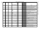
BypTime nciAux2SetPt uiBypassTime minutes
0 to 1080
180 P X X uiBypassTime is the time between the pressing of the override
button at the wall module (or initiating OC_BYPASS via ManOcc)
and the return to the original occupancy state. When the bypass
state has been activated, the bypass timer is set to BypassTime.
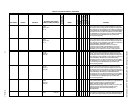
FltrPressStPt nciAux2SetPt ubFilterPressStPtS5 inw (kPa)
0 to 5 (0 to 1.25)
0.5 P X X If a filter pressure sensor is configured by IoSelect and the filter
pressure reported in Data1 FilterPressure exceeds FilterPressStPt,
then a DIRTY_FILTER alarm is generated and Data1.DirtyFilter is
set to 1.
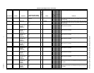
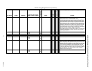
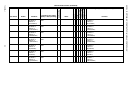
StptKnobLowLim nciAux2SetPt siLowStPtS7 Degrees F
-9 to 90
Degrees C
(-23 to 32)
55 P X X LowStPt is the lowest value reported for the setpoint knob.
Dependent on the configuration of the setpoint knob (see
Config.SetPntKnob) this setting is either absolute [degree
Fahrenheit (50 to 90)] in case of absolute setpoint knob configuration
or relative [delta degree Fahrenheit (-9 to +9)] in case of relative
setpoint knob configuration.
StptKnobHiLim nciAux2SetPt siHighStPtS7 Degrees F
-9 to 90
Degrees C
(-23 to 32)
85 P X X HighStPt is the highest value reported for the setpoint knob.
Dependent on the configuration of the setpoint knob (see
Config.SetPntKnob) this setting is either absolute [degree
Fahrenheit (50 to 90)] in case of absolute setpoint knob configuration
or relative [delta degree Fahrenheit (-9 to +9)] in case of relative
setpoint knob configuration.
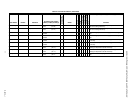
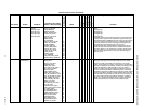
Table 21. Control Parameters. (Continued)
User Address NvName Field Name
Engineering Units: English
(Metric) or States plus Range
Digital State or
Value of State
Default
E-Vision (M, P, S)
Share
Map
Direct Access
Hardware Config.
Manual Config.
Test
E-Vision Legend: (M) Monitor, (P) Parameter, (S) Schematic
Comments