


EXCEL 10 W7750A,B,C CONSTANT VOLUME AHU CONTROLLER
74-2958—150
NOTE: The node can be reset b
y
switchin
g
the node to
MANUAL and then to the normal operatin
g
mode
(
see Fan Operation in Appendix B
)
.
Also, the Excel 10 variables,
AlarmLogX
where
X
is 1 throu
g
h
5, that store the last five alarms to occur in the controller, are
available. These points can be viewed throu
g
h XBS or
E-Vision.
Certain alarm conditions are suppressed conditionall
y
as
follows:
Broadcasting the Service Message
The Service Messa
g
e allows a device on the L
ON
W
ORKS
Bus
to be positivel
y
identified. The Service Messa
g
e contains the
controller ID number and, therefore, can be used to confirm
the ph
y
sical location of a particular Excel 10 in a buildin
g
.
There are three methods of broadcastin
g
the Service
Messa
g
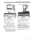
e from an Excel 10 W7750 Controller. One uses a
hardware service pin button on the side of the controller
(
see
Fi
g
. 41
)
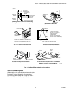
. The second uses the wall module pushbutton
(
see
Fi
g
. 43 and 44
)
. B
y
pressin
g
the wall module pushbutton for
more than four seconds, the controller sends out the Service
Messa
g
e. The third involves usin
g
the PC Confi
g
uration tool,
as follows.
When an
Assign ID
command is issued from the
commissionin
g
tool, the node
g
oes into the
SERVICE_MESSAGE mode for five minutes. In the
SERVICE_MESSAGE mode, pressin
g
the Occupanc
y
Override button on the remote wall module
(
refer to Fi
g
. 43
and 44 for override button location
)
causes the Service
Messa
g
e to be broadcast on the network. All other functions
are normal in the SERVICE_MESSAGE mode. Even if an
Excel 10 W7750 Controller does not have an Override button
connected, it can broadcast the Service Messa
g
e on the
network b
y
temporaril
y
shortin
g
the Controller B
y
pass Input
terminal to the Sensor Ground terminal on the W7750A,B,C
(
short terminals 3 and 5
)
.
The commissionin
g
tool is used to perform the ID Assi
g
nment
task
(
see the E-Vision User’s Guide, form 74-2588
)
.
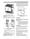
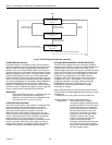
Fig. 41. Location of the Service Pin Button.
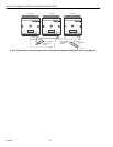
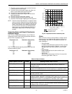
W7750 Controller Status LED
The LED on the front and center of a W7750 Controller
provides a visual indication of the status of the device. See
Fi
g
. 42. When the W7750 receives power, the LED should
appear in one of the followin
g
allowable states:
1.
Off—no power to the processor.
2.
Continuousl
y
On—processor is in initialized state.
3.
Slow Blink—controllin
g
, normal state.
4.
Fast Blink—when the Excel 10 has an alarm condition.
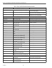
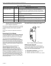
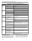
LOSS_OF_AIR_FLOW 6 The Fan Status DI indicates that there is no air flow when the node is
commandin
g
the fan to run. The control is shut down and disabled until power is
c
y
cled or the node is reset. See NOTE below. The alarm is not issued until
FanFailTime seconds have elapsed since the loss-of-flow condition was first
reported
DIRTY_FILTER 7 The pressure drop across the filter exceeds the limit and the filter re
q
uires
maintenance. The control runs normall
y
.
SMOKE_ALARM 8 The smoke detector has detected smoke and the node has entered an
emer
g
enc
y
state.
IAQ_OVERRIDE 9 The indoor air
q
ualit
y
sensor has detected that the indoor air
q
ualit
y
is less than
the desired standard and additional outdoor air is bein
g
brou
g
ht into the
conditioned space.
LOW_LIM_ECON_CLOSE 10 The economizer has to close be
y
ond the minimum position to prevent the
dischar
g
e air temperature from
g
oin
g
below the dischar
g
e temperature low limit.
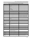
Table 12. Excel 10 Alarms. (Continued)
Name of alarm or error bit
Alarm type
number Meaning of alarm code or error bit
M10094
SERVICE
PIN
BUTTON