


EXCEL 10 W7750A,B,C CONSTANT VOLUME AHU CONTROLLER
74-2958—152
Occasionall
y
, the PID parameters re
q
uire tunin
g
to optimize
comfort and smooth e
q
uipment operation. This applies to the
W7750A,B,C Controllers.
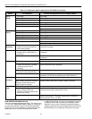
CVAHU Controllers are confi
g
ured b
y
E-Vision with default
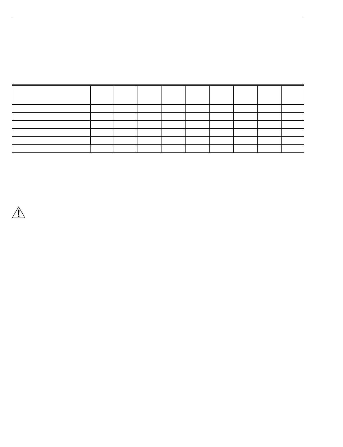
values of PID parameters as shown in Appendix C Table 21. If
different values for these parameters are desired, Table 13
lists some recommended values to use as a startin
g
point.
These recommended values are based on past experience
with the applications and in most cases do not re
q
uire further
ad
j
ustment.
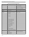
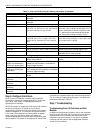
Table 13. Recommended Values For PID Parameters.
If the PID parameters re
q
uire ad
j
ustment awa
y
from these
values,
use caution
to ensure that e
q
uipment problems do not
arise
(
see CAUTION below
)
. If an
y
chan
g
e to PID control
parameters is made, the ad
j
ustments should be
g
radual. After
each chan
g
e, the s
y
stem should be allowed to stabilize so the
effects of the chan
g
e can be accuratel
y
observed. Then
further refinements can made, as needed, until the s
y
stem is
operatin
g
as desired.
CAUTION
If lar
g
e or fre
q
uent chan
g
es to PID control parameters
are made, it is possible to cause e
q
uipment problems
such as short c
y
clin
g
compressors
(
if the sta
g
e
minimum run times were disabled in User Addresses
DisMinClTime or DisMinHtTime
)
. Other problems that
can occur include wide swin
g
s in space temperature
and excessive overdrivin
g
of modulatin
g
outputs.
If ad
j
ustment of PID parameters is re
q
uired, use the followin
g
.
In the items that follow, the term, error, refers to the difference
between the measured space temperature and the current
actual space temperature setpoint.
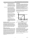
— The
Proportional Gain
(
also called Throttlin
g
Ran
g
e
)
determines how much impact the error has on the output
si
g
nal. Decreasin
g
the Proportional Gain amplifies the
effect of the error; that is, for a
g
iven error, a small
Proportional Gain causes a hi
g
her output si
g
nal value.
— The
Integral Gain
(
also called Inte
g
ral Time
)
determines
how much impact the error-over-time has on the output
si
g
nal. Error-over-time has two components makin
g
up its
value: the amount of time the error exists; and the size of
the error. The hi
g
her the Inte
g
ral Gain, the slower the
control response. In other words, a decrease in Inte
g
ral
Gain causes a more rapid response in the output si
g
nal.
— The
Derivative Gain
(
also called Derivative Time
)
determines how much impact the error rate has on the
output si
g
nal. The error rate is how fast the error value is
chan
g
in
g
. It can also be the direction the space
temperature is
g
oin
g
, either toward or awa
y
from the
setpoint, and its speed—
q
uickl
y
or slowl
y
. A decrease in
Derivative Gain causes a
g
iven error rate to have a lar
g
er
effect on the output si
g
nal.
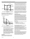
— The
Control Band
is used onl
y
for dischar
g
e temperature
control of modulatin
g
outputs, which includes controllin
g
the economizer dampers, and heatin
g
and coolin
g
valves
usin
g
Cascade Control. The Control Band dictates the
span throu
g
h which the dischar
g
e temperature must travel
to cause the output si
g
nal to
g
o from full
y
closed to full
y
open. Also, 10 percent of the Control Band value is the size
of the
deadband
around the setpoint where no actuator
motion occurs. For example, if controllin
g
a coolin
g
valve
with Cascade Control enabled and with the dischar
g
e
temperature within 0.1 X DaTempClCtrlBd of the dischar
g
e
setpoint, there is no chan
g
e in the current valve position.
The smaller the Control Band, the more responsive the
control output. A lar
g
er Control Band causes more slu
gg
ish
control. Be careful not to set the Control Band too low and
cause lar
g
e over or under shoots
(
huntin
g)
. This can
happen if the space or dischar
g
e sensors or wirin
g
are in
nois
y
environments and the value reported to the controller
is not stable
(
such that it bounces
)
. The Control Band is
used onl
y
in modulatin
g
control, and has no purpose when
sta
g
ed control is confi
g
ured.
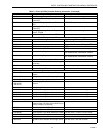
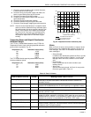
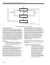
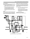
Appendix B. Sequences of Operation.
This Appendix provides the control se
q
uences of operation for
the models of the Excel 10 W7750 CVAHU Controller. The
W7750A,B,C Controllers can be confi
g
ured to control a wide
variet
y
of possible e
q
uipment arran
g
ements. Table 14 and 15
(
copied from Tables 3 and 4
)
summarize the available options.
This Appendix provides a more detailed discussion of these
options.
Equipment Configuration
Heat
Prop.
Gain
Heat
Integ.
Gain
Heat
Deriv.
Gain
Heat
Control
Band
Cool
Prop.
Gain
Cool
Integ.
Gain
Cool
Deriv.
Gain
Cool
Control
Band
Econ
Control
Band
Single Stage
2 3000 0 10 2 3000 0 10 10
Two Stages
3 2000 0 10 3 2000 0 10 10
Three Stages
4.5 1500 0 10 4.5 1500 0 10 10
Four Stages
6 1000 0 10 6 1000 0 10 10
Series 60 Modulating (Floating)
2 750 0 10 2 750 0 10 10
PWM Modulating
2 900 0 10 2 900 0 10 10