


EXCEL 10 W7750A,B,C CONSTANT VOLUME AHU CONTROLLER
37 74-2958—1
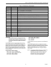
Table 10. W7750A Version I/O Description.
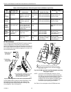
IMPORTANT
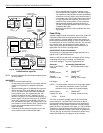
If the W7750A controller is configured by E-Vision,
the outputs may be assigned in different order than
the factory defaults. Use the Custom Wiring function
of E-Vision to re-assign the outputs to the desired
terminals.
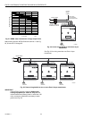
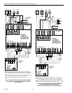
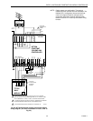
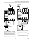
The W7750B,C Versions are preconfi
g
ured with the same
factor
y
default setup as the W7750A Model; however, some
terminals for wirin
g
connections differ on the W7750B,C
Models. See Fi
g
. 30 for the terminal names on the W7750B
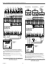
Model and Fi
g
. 35 for the terminal names on the W7750C
Model. The factor
y
default confi
g
uration of the di
g
ital output
points on the W7750B,C Models follow
(
terminal names are
from the W7750A
)
:
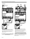
FACTORY DEFAULT DIGITAL OUTPUTS:
FREE 1
(
OUT 1
)
DO1—NETWORK DO
(
OUT 2
)
DO2—SUPPLY FAN START/STOP
(
OUT 3
)
DO3—COOL_STAGE_2
(
OUT 4
)
DO4—COOL_STAGE_1
(
OUT 5
)
DO5—HEAT_STAGE_2
(
OUT 6
)
DO6—HEAT_STAGE_1
DO7—UNUSED
DO8—UNUSED
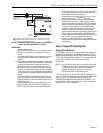
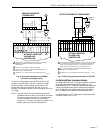
The Wall Module terminals are identical for the W7750A,B,C
Models.
The W7750B,C Models offers two volta
g
e/current sensor
input terminals. When current-t
y
pe sensors
(
4 to 20 mA
)
are
confi
g
ured, the W7750B,C automaticall
y
switches a 249 ohm
resistor into the sensin
g
circuit; so no external resistor is
re
q
uired. The W7750A Model does not support volta
g
e or
current inputs.
NOTE: If usin
g
factor
y
defaults, DI-2 input is confi
g
ured for
ScheduleMaster
(
nvoIO.SchedMaster
)
. For a
stand-alone unit, either connect an external time
clock to terminals 9 and 10 or put a
j
umper on
terminals 9 and 10
(
usin
g
a
j
umper puts the
controller in continuous occupied mode
)
.
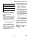
Terminal Terminal Number Description
DO6–
(
W1
)
31 Heat 1
(
or Reversin
g
Valve for a Heat Pump
)
DO5–
(
W2
)
30 Heat 2
(
or Aux. Heat for a Heat Pump
)
DO4–
(
Y1
)
29 Cool 1
(
or Compressor 1 for a Heat Pump
)
DO3–
(
Y2
)
28 Cool 2
(
or Compressor 2 for a Heat Pump
)
DO2–
(
G
)
27 Fan
DO1–NET 26 Network Di
g
ital Output
DO1–NET 25 Network Di
g
ital Output
(
connect to terminal number 22 +24Vac
)
Rc 24 Control power for rela
y
contacts DO2
(
G
)
, DO3
(
Y1
)
and DO4
(
Y2
)
Rh 23 Control power for rela
y
contacts DO5
(
W1
)
and DO6
(
W2
)
+24Vac
(
H
)
22 Power for the controller
COM
(
N
)
21 Return for power to controller
E-Bus 14 and 15 Echelon communications
(
L
ON
W
ORKS
Bus
)
screw terminals
DI - 2 12 Di
g
ital Input 2
DGND 11 Di
g
ital Ground
DGND 10 Di
g
ital Ground
DI - 1 9 Di
g
ital Input 1
AGND 8 Analo
g
g
round
AI - 1 OHM 7 Analo
g
Input 1
(
used for Dischar
g
e Air Temperature Sensor
)
SET PT 6 Space temperature setpoint potentiometer
GROUND 5 Wall Module
SENSOR 4 Space temperature sensor
BYPASS 3 Space override button
LED 2 Space LED for indication of manual occupanc
y
status
EARTH GND 1 Earth Ground