


EXCEL 10 W7750A,B,C CONSTANT VOLUME AHU CONTROLLER
74-2958—136
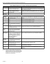
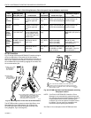
Table 9. Field Wiring Reference Table (Honeywell listed as AK#### or equivalent).
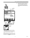
W7750 Controllers
Fi
g
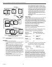
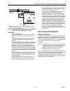
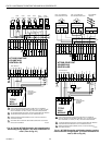
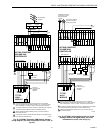
. 27 throu
g
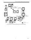
h 35 illustrate W7750A,B,C Controller wirin
g
for
various confi
g
urations. Connections to the wall module
terminals
(
2 throu
g
h 6
)
and the communications terminals
(
14
and 15
)
are made at terminal blocks. Connection for access to
the L
ON
W
ORKS
Bus is provided b
y
plu
gg
in
g
the connector into
the communications
j
ack.
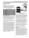
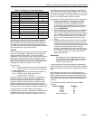
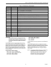
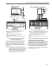
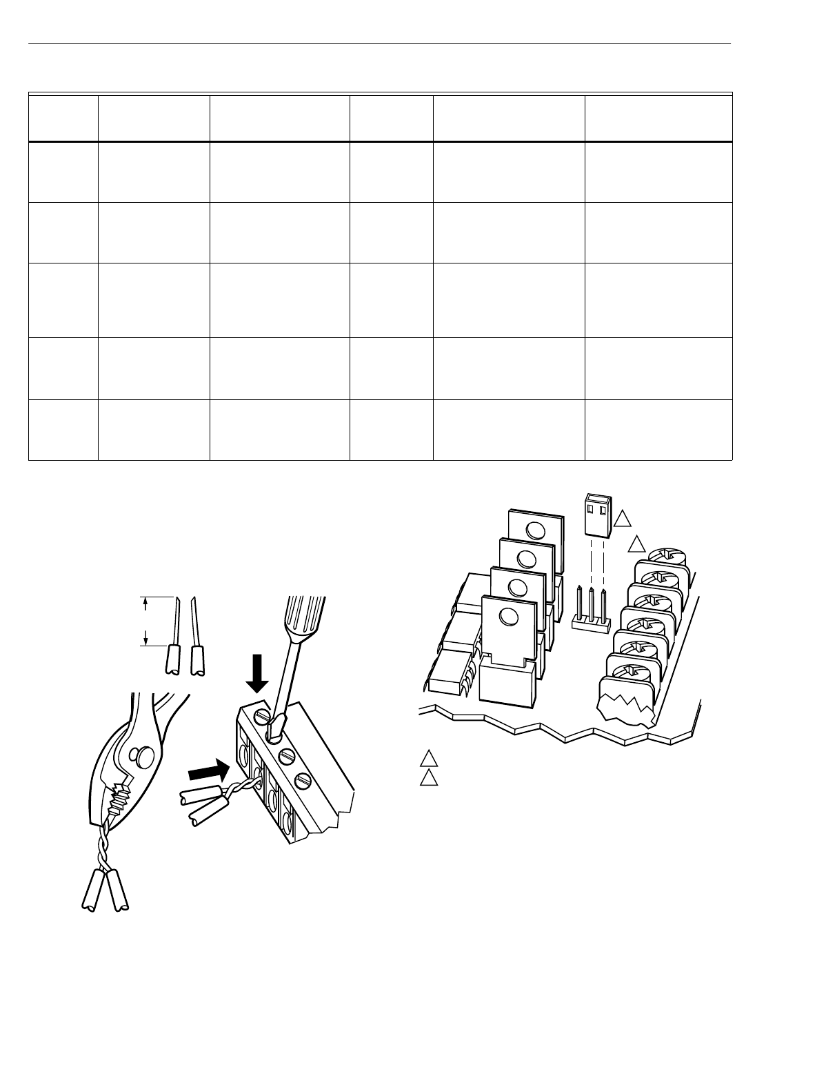
Fig. 25. Attaching two or more wires at terminal blocks.
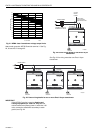
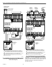
The W7750B provides a
j
umper to select Hi
g
h-Side or Low-
Side switchin
g
of the di
g
ital outputs. Fi
g
. 26 shows the
W7750B Hi
g
h-Side/Low-Side selectable switchin
g
.
(
See
wirin
g
dia
g
rams, Fi
g
s. 30 throu
g
h 34.
)
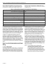
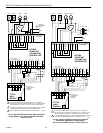
Fig. 26. W7750B High-Side/Low-Side selectable switching
and jumper location.
NOTE: If an Excel 10 W7750A,B,C Controller or Zone
Mana
g
er is not connected to a
g
ood earth
g
round,
the controller internal transient protection circuitr
y
is
compromised and the function of protectin
g
the
controller from noise and power line spikes cannot
be fulfilled. This can result in a dama
g
ed circuit
board and re
q
uire replacin
g
the controller.
See Table 10 for a description of the W7750A terminals.
Wire
Function
Recommended
Minimum Wire
Size AWG (mm
2
) Construction
Specification
or
Requirement Vendor Wire Type
Maximum Length ft.
(m)
L
ON
W
ORKS
Bus
(Plenum)
22 AWG
(
0.34 mm
2
)
Twisted pair solid
conductor, nonshielded
or Echelon approved
cable.
Level IV
140°F
(
60°C
)
ratin
g
Hone
y
well
AK3791
(
one twisted pair
)
AK3792
(
two twisted pairs
)
Refer to L
ON
W
ORKS
Bus
Wirin
g
Guidelines for
maximum len
g
th
L
ON
W
ORKS
Bus (Non-
Plenum)
22 AWG
(
0.34 mm
2
)
Twisted pair solid
conductor, nonshielded
or Echelon approved
cable.
Level IV
140°F
(
60°C
)
ratin
g
Hone
y
well
AK3781
(
one twisted pair
)
AK3782
(
two twisted pairs
)
Refer to L
ON
W
ORKS
Bus
Wirin
g
Guidelines for
maximum len
g
th
Input
Wiring
Sensors
Contacts
18 to 22 AWG
(
1.0 to 0.34 mm
2
)
Multiconductor
(
usuall
y
five-wire cable bundle
)
.
For runs >200 ft.
(
61m
)
in nois
y
EMI areas, use
shielded cable.
140°F
(
60°C
)
ratin
g
Standard thermostat wire 1000 ft.
(
305m
)
for 18
AWG 200 ft.
(
61m
)
for 22
AWG
Output
Wiring
Actuators
Relays
14 AWG
(
2.0 mm
2
)
18 AWG
(
1.0 mm
2
)
acceptable for
short runs
)
An
y
pair nonshielded
(
use heavier wire for
lon
g
er runs
)
.
NEC Class 2
140°F
(
60°C
)
ratin
g
Hone
y
well
AK3702
(
18 AWG
)
AK3712
(
16 AWG
)
AK3754
(
14 AWG
)
Limited b
y
line-loss
effects on power
consumption.
(
See Line
Loss subsection.
)
Power
Wiring
14 AWG
(
2.0 mm
2
)
An
y
pair nonshielded
(
use heavier wire for
lon
g
er runs
)
.
NEC Class 2
140°F
(
60°C
)
ratin
g
Hone
y
well
AK3754
(
14 AWG
)
twisted
pair AK3909
(
14 AWG
)
sin
g
le conductor
Limited b
y
line-loss
effects on power
consumption.
(
See Line
Loss subsection.
)
1/2
(13)
STRIP 1/2 IN. (13 MM)
FROM WIRES TO
BE ATTACHED AT
ONE TERMINAL.
1.
2.
TWIST WIRES
TOGETHER WITH
PLIERS (A MINIMUM
OF THREE TURNS).
3. CUT TWISTED END OF WIRES TO 3/16 IN. (5 MM)
BEFORE INSERTING INTO TERMINAL AND
TIGHTENING SCREW. THEN PULL ON EACH
WIRE IN ALL TERMINALS TO CHECK FOR
GOOD MECHANICAL CONNECTION.
M17207
U3
Q38
J2
JUMPER
TERMINAL 24
J2 IS LOCATED NEAR TERMINAL 24 (COVER REMOVED).
W7750B IS FACTORY-DELIVERED WITH JUMPER ON HIGH-SIDE
(PINS CLOSEST TO TERMINAL BLOCK). LOW-SIDE PINS ARE TWO
PINS CLOSEST TO Q38.
1
1
2
2
M16418A