


EXCEL 10 W7750A,B,C CONSTANT VOLUME AHU CONTROLLER
51 74-2958—1
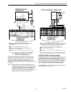
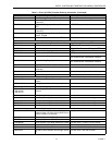
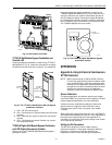
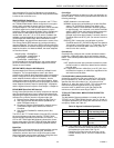
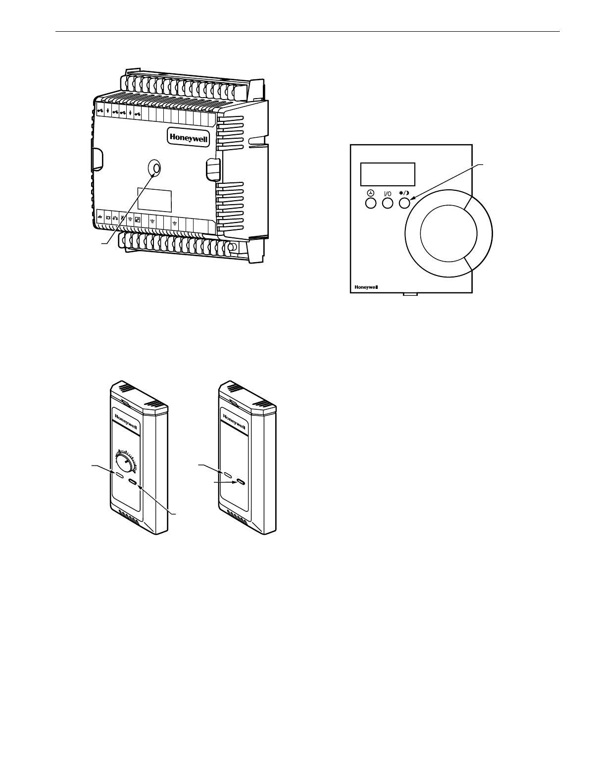
Fig. 42. LED location on W7750.
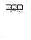
T7770C,D Wall Module Bypass Pushbutton and
Override LED
Pressin
g
the b
y
pass pushbutton, located on the T7770C,D
Wall Modules in Fi
g
. 43, causes the override LED to displa
y
the Manual Override mode of the controller. The modes are:
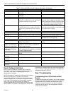
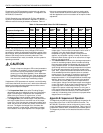
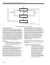
Fig. 43. The T7770C,D Wall Modules LED and Bypass
pushbutton locations.
1.
LED = Off. No override active.
2.
LED = Continuousl
y
on. B
y
pass mode
(
timed Occupied
override
)
.
3.
LED = One flash per second. Continuous Unoccupied
override.
4.
LED = Two flashes per second. Remote onl
y
, continu-
ous Occupied override.
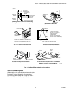
T7560A,B Digital Wall Module Bypass Pushbutton
and LCD Display Occupancy Symbols
See Fi
g
. 44 for the T7560A,B Di
g
ital Wall Module b
y
pass
pushbutton location.
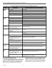
Press and release the b
y
pass pushbutton, located on the
T7560A,B Di
g
ital Wall Modules in Fi
g
. 44 for more than one
second to cause the sun s
y
mbol on the bottom ri
g
ht side of
the LCD displa
y
to appear. Pressin
g
the b
y
pass pushbutton
for more than four seconds causes the controller, hard-wired
to the T7560A,B, to
g
o into continuous unoccupied override.
The T7560A,B displa
y
s the moon s
y
mbol.
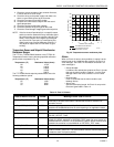
Fig. 44. The T7560A,B Digital Wall Module Bypass
pushbutton location.
APPENDICES
Appendix A. Using E-Vision to Commission a
W7750 Controller.
NOTE: When commissionin
g
a CVAHU W7750 Controller,
E-Vision first checks that the actual hardware model
(
such as W7750A,B,C
)
is the same t
y
pe which was
selected from the Application Selection/Output tab. If
the t
y
pes do not match, the download does not occur
and the user-entered values in the Application
Selection screens all revert back to default values.
Sensor Calibration
The space temperature, the optional resistive and
voltage/
current
(
W7750B,C onl
y)
inputs can all be calibrated. The wall
module setpoint potentiometer
can not
be calibrated.
Perform the sensor calibration b
y
addin
g
an offset value
(
either positive or ne
g
ative
)
to the sensed value usin
g
E-Vision menus
(
see E-Vision user
g
uide, form number
74-2588
)
.
When calibratin
g
volta
g
e/current sensors on the
(
W7750B,C
)
,
the offset amount entered b
y
the user is in volts, re
g
ardless of
the inputs actual en
g
ineerin
g
units. See Appendix E for
information on how to derive the proper volta
g
e value to enter
as an offset durin
g
calibration.
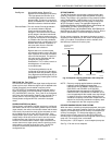
Setting the Pid Parameters
The W7750 is desi
g
ned to control a wide variet
y
of
mechanical s
y
stems in man
y
t
y
pes of buildin
g
s. With this
flexibilit
y
, it is necessar
y
to verif
y
the stabilit
y
of the
temperature control in each different t
y
pe of application.
M10095A
W7750
1
23
456
789
1
0111
2131
4
1
5
J
3
31 3
0292
8272
625242
3222
1201
918171
6
E
GND
LED BYPASS
SNSR
SET PT AI-1
OHM
A1-2
OHM
AI-3
V/mA
AI-4
V/mA
20VDC
OUT
DI-4
D
I
-
3
DI-2
DI-1
VAC
24
VAC
24
COM
1
OUT
2
OUT
3
O
UT
4
OUT
5
OUT
6
O
UT
7
OUT
8
OUT
A
I
G
N
D
A
I
G
N
D
A
I
G
N
D
L
O
N
W
O
R
K
S
-
B
U
S
L
O
N
J
A
C
K
D
I
G
N
D
D
I
G
N
D
STATUS
LED
M11617
T7770C
T7770D
OVERRIDE
LED
BYPASS
PUSHBUTTON
BYPASS
PUSHBUTTON
7
0
6
5
6
0
5
5
7
5
8
0
8
5
OVERRIDE
LED
M17500
BYPASS
PUSHBUTTON