EXCEL 10 W7750A,B,C CONSTANT VOLUME AHU CONTROLLER
74-2958—122
Configurations
General
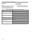
Tables 3 and 4 provide an overview of the Excel 10 W7750
confi
g
uration options. All W7750s are assumed to have a
suppl
y
fan di
g
ital output. Additionall
y
, Tables 3 and 4 list the
g
eneral mechanical e
q
uipment options available with the
W7750 Controller. See Application Step 6. Confi
g
ure
Controllers, for further information on confi
g
urations.
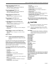
CAUTION
For floatin
g
control, the Excel 10 W7750 Controller is
desi
g
ned to work onl
y
with Series 60 valve and
damper actuators. Full stroke actuator drive-time must
be between 20 and 240 seconds
(
0.25 to 4.0 minutes
)
.
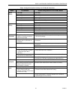
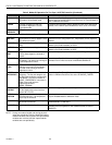
Table 3. Common Configuration Options Summary For W7750A,B,C Controllers.
Option Possible Configurations Common To All W7750 Models
Supply Fan
1. Mandator
y
Di
g
ital Output.
Type of Air Handler
1. Conventional.
2. Heat Pump.
Occupancy Sensor
1. None.
2. Connected: Contacts closed e
q
uals Occupied.
3. Network
(
Occ/Unocc si
g
nal received via the L
ON
W
ORKS
Bus network
)
.
Window Sensor
1. None.
2. Ph
y
sicall
y
Connected: Contacts closed e
q
uals window closed.
3. Network
(
Window Open/Closed si
g
nal received via the L
ON
W
ORKS
Bus
)
.
Wall Module Option
1. Local
(
direct wired to the controller
)
.
(
The T77560A,B has no L
ON
W
ORKS
Bus access
)
2. Network
(
sensor value received via the L
ON
W
ORKS
Bus
)
.
Wall Module Type
1. Sensor onl
y
.
(
All wall modules have a L
ON
W
ORKS
Bus access 2. Sensor and Setpoint ad
j
ust.
j
ack except T7560A,B
)
3. Sensor, Setpoint ad
j
ust and B
y
pass.
4. Sensor and B
y
pass.
Smoke Emergency
Initiation
1. None.
2. Ph
y
sicall
y
Connected: Contacts closed e
q
uals smoke detected.
3. Network
(
Emer
g
enc
y
/Normal si
g
nal received via the L
ON
W
ORKS
Bus
)
.


