


EXCEL 10 W7750A,B,C CONSTANT VOLUME AHU CONTROLLER
23 74-2958—1
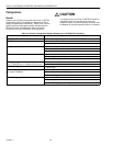
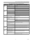
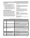
Table 4. Configuration Options Summary For W7750A,B,C Controllers.
Option
Possible Configurations for the
W7750A Model Possible Configurations for the W7750B,C Models
Type of
1. One sta
g
e. 1. One sta
g
e.
Heating
2. Two sta
g
es. 2. Two sta
g
es.
3. Three sta
g
es. 3. Three sta
g
es.
4. Four sta
g
es. 4. Four sta
g
es.
5. None. 5. Series 60 Modulatin
g
electric valve, or pneumatic via transducer.
6. Pulse Width Modulatin
g
electric valve, or pneumatic via transducer.
7. None.
Type of
1. One sta
g
e. 1. One sta
g
e.
Cooling
2. Two sta
g
es. 2. Two sta
g
es.
3. Three sta
g
es. 3. Three sta
g
es.
4. Four sta
g
es. 4. Four sta
g
es.
5. None. 5. Series 60 Modulatin
g
electric valve, or pneumatic via transducer.
6. Pulse Width Modulatin
g
electric valve, or pneumatic via transducer.
7. None.
Type of
Economizer
1. Di
g
ital Output Enable/Disable
si
g
nal for controllin
g
an external
economizer packa
g
e.
1. Di
g
ital Output Enable/Disable si
g
nal for controllin
g
an external
economizer packa
g
e.
2. Series 60 Modulatin
g
electric
damper motor, or pneumatic via
transducer.
2. Series 60 Modulatin
g
electric damper motor, or pneumatic via
transducer.
3. None. 3. Pulse Width Modulatin
g
electric damper motor, or pneumatic via
transducer.
4. None.
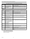
IAQ Option
1. None. 1. None.
2. Local IAQ Di
g
ital Input—directl
y
wired to the controller.
(
Contacts
closed means poor IAQ is
detected.
)
2. Local IAQ Di
g
ital Input—directl
y
wired to the controller.
(
Contacts
closed means poor IAQ is detected.
)
3. Network
(
IAQ Override si
g
nal
received via the L
ON
W
ORKS
Bus
)
.
3. Network
(
IAQ Override si
g
nal received via the L
ON
W
ORKS
Bus
)
.
4. Local CO
2
Analo
g
Input—directl
y
wired to the controller.
(
The sensor
must be a 0 to 10V device representin
g
0 to 2000 PPM CO
2
.
)
Coil Freeze
1. None. 1. None.
Stat Option
2. Local Coil Freeze Stat Di
g
ital
Input—directl
y
wired to the controller.
(
Contacts closed means that coil
freeze condition is sensed.
)
2. Local Coil Freeze Stat Di
g
ital Input—directl
y
wired to the controller.
(
Contacts closed means that coil freeze condition is sensed.
)
Filter Monitor
1. None. 1. None.
Option
2. Local Dirt
y
Filter Di
g
ital
Input—directl
y
wired to the
controller.
(
Contacts closed means
that the filter is dirt
y
.
)
2. Local Dirt
y
Filter Di
g
ital Input—directl
y
wired to the controller.
(
Contacts closed means that the filter is dirt
y
.
)
3. Local Analo
g
Input for Differential Pressure across the Filter
(
directl
y
wired to the controller
)
. The sensor must be a 2 to 10V device
representin
g
0 to 5 inw
(
1.25 kPa
)
.