


EXCEL 10 W7750A,B,C CONSTANT VOLUME AHU CONTROLLER
74-2958—158
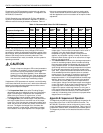
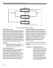
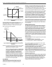
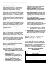
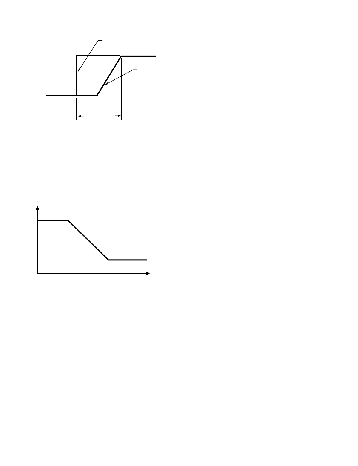
Fig. 47. Setpoint ramping parameters with setpoint
calculation.
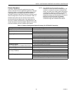
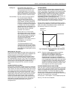
Durin
g
the COOL recover
y
period, the setpoint chan
g
es at a
rate in de
g
rees per hour relative to the outdoor air
temperature. If there is no outdoor air temperature sensor
available, the MinClRamp is used as the recover
y
rate.
See Fi
g
. 48 for the various setpoints.
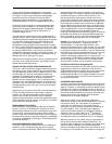
Fig. 48. Setpoint ramping parameters with ramp rate
calculation.
NOTES: The setpoint used durin
g
the COOL recover
y
period
is similar to the heat mode in Fi
g
. 46, except the
slope of the line reverses for coolin
g
.
Recover
y
rampin
g
applies between scheduled heat-
in
g
or coolin
g
setpoint chan
g
es from UNOCCUPIED
to STANDBY, UNOCCUPIED to OCCUPIED, and
STANDBY to OCCUPIED. Scheduled setpoint
chan
g
es from OCCUPIED to UNOCCUPIED or
OCCUPIED to STANDBY do not use a ramped set-
point, but instead, use a step chan
g
e in setpoint.
Recover
y
ramps be
g
in before the next scheduled
occupanc
y
time and are ramped from the setpoint for
the existin
g
scheduled occupanc
y
state to the set-
point for the next occupanc
y
state.
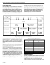
FAN OPERATION
The W7750 suppl
y
fan can be controlled in one of two
different wa
y
s. In Continuous Fan mode, the fan runs
whenever the controller is in Occupied mode. When in
Standb
y
or Unoccupied modes, the fan c
y
cles on with a call
for coolin
g
(
or heatin
g
if the FanOnHtMode parameter is set
)
.
In Intermittent Fan mode, the fan c
y
cles on with a call for
coolin
g
(
or heatin
g
if the FanOnHtMode parameter is set
)
, and
c
y
cles off when the space temperature control is satisfied.
The fan control supports an optional
(
Proof of Air Flow
)
di
g
ital
input, that allows monitorin
g
of the suppl
y
fans status. If the
fan is commanded on, the Proof of Air Flow di
g
ital input is
checked up to three times to verif
y
that the fan is runnin
g
after
an initial dela
y
of FanOnDela
y
seconds
(
user-settable
)
. If the
fan fails to start the CVAHU must be reset b
y
first c
y
clin
g
CVAHU power. If this does not work, set DestManMode to
Manual and then back to Enable. After a reset the application
restarts—all outputs switch off and auto control is enabled.
Also, the W7750 Controller provides fan-run-on operation that
keeps the fan runnin
g
for a short time after heatin
g
or coolin
g
shuts off. The amount of time that the fan continues to run is
set in FanRunOnHeat for heatin
g
mode and FanRunOnCool
for coolin
g
mode.
WINDOW SENSOR (StatusWndw)
The di
g
ital input for a window contact provides the al
g
orithm
with a means to disable its temperature control activities if
someone has opened a window or door in the room. When a
window is detected to be Open
(
di
g
ital input contacts Open
e
q
uals window open
)
, the normal temperature control is
disabled, and the W7750 Controller enters the Freeze Protect
mode. Freeze Protect mode sets the space setpoint to 46.4 °F
(
8°C
)
and brin
g
s on the fan and heat if the space temperature
falls below this setpoint. Normal temperature control resumes
on window closure. The Window sensor si
g
nal can also be a
network input from another L
ON
W
ORKS
Bus device, so that no
ph
y
sical sensor is re
q
uired at the receivin
g
W7750 Controller.
SMOKE CONTROL
The Excel 10 W7750 Controller supports three smoke-related
control strate
g
ies:
1.
Emer
g
enc
y
Shutdown
(
all outputs off
)
.
2.
Depressurize
(
fan on, outdoor air damper closed
)
.
3.
Pressurize
(
fan on, outdoor air damper open
)
.
The controller is placed in one of these three control states
whenever the W7750 mode becomes
SMOKE_EMERGENCY, which can be initiated via a network
command
(
DestEmer
g
Cmd
)
or from a local
(
ph
y
sicall
y
connected
)
smoke detector di
g
ital input. When in
SMOKE_EMERGENCY mode, the W7750 Controller uses the
control strate
gy
found in SmkCtlMode
(
one of the three listed
above
)
, and the normal temperature control function is
disabled. If a W7750 local smoke detector trips, the SrcEmer
g
network variable
(
for other L
ON
W
ORKS
Bus devices to receive
)
is set to the Emer
g
enc
y
state.
DEMAND LIMIT CONTROL (DLC)
When The L
ON
W
ORKS
Bus network receives a hi
g
h-electrical-
demand si
g
nal, the controller applies a DlcBumpTemp amount
to the current actual space temperature setpoint value. The
setpoint is alwa
y
s ad
j
usted in the ener
gy
-savin
g
direction.
This means that if the W7750 Controller is in Coolin
g
mode,
the DLC offset bumps the control point up, and when in
Heatin
g
mode, bumps the control point down.
OCC setpoint
UN_OCC setpoint
OR
STANDBY setpoint
M10110
AUX HEAT
SETPOINT
HEAT PUMP
SETPOINT
(FOR COMPRESSORS)
RECOVERY TIME
OCCUPIED TIME
COOL RECOVERY
RAMP RATE
(DEGREES/HOUR)
MaxClRam
MinClRam
OaTempMinClRa OaTempMaxClRam
OUTDOOR AIR
TEMPERATURE
M10111