


EXCEL 10 W7750A,B,C CONSTANT VOLUME AHU CONTROLLER
29 74-2958—1
APPLICATION STEPS
Overview
The seven application steps shown in Table 6 are plannin
g
considerations for en
g
ineerin
g
an Excel 10 W7750 S
y
stem.
These steps are
g
uidelines intended to aid understandin
g
of
the product I/O options, bus arran
g
ement choices,
confi
g
uration options and the Excel 10 W7750 Controller role
in the overall EXCEL 5000
OPEN
SYSTEM architecture.
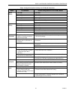
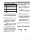
Table 6. Application Steps.
Step 1. Plan the System
Plan the use of the W7750 Controllers accordin
g
to the
j
ob
re
q
uirements. Determine the location, functionalit
y
and sensor
or actuator usa
g
e. Verif
y
the sales estimate of the number of
W7750 Controllers, T7770 and T7560 Wall Modules re
q
uired
for each model t
y
pe. Also check the number and t
y
pe of
output actuators and other re
q
uired accessories.
When plannin
g
the s
y
stem la
y
out, consider potential
expansion possibilities to allow for future
g
rowth. Plannin
g
is
ver
y
important to be prepared for addin
g
HVAC s
y
stems and
controllers in future pro
j
ects.
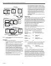
T7560 Wall Modules can onl
y
be hard-wired, the
y
have no
L
ON
W
ORKS
Bus access. T7770 Wall Modules can be installed
as either hard-wired I/O-onl
y
devices or additional wirin
g
can
be run to them
(
for the L
ON
W
ORKS
Bus network
)
to allow a
CARE/E-Vision operator terminal to have access to the
L
ON
W
ORKS
Bus. The application en
g
ineer needs to determine
how man
y
wall modules, T7770s and T7560s are re
q
uired. All
T7770 Wall Modules, except the T7770A1006 and the
T7770A1014, can be connected via the L
ON
W
ORKS
Bus
j
ack.
Also the application en
g
ineer needs to know how man
y
T7770s without L
ON
W
ORKS
Bus network connections are
bein
g
installed on the
j
ob, and then clearl
y
document which
wall modules
(
if an
y)
have network access. This information is
re
q
uired durin
g
installation to ensure that the proper number
and t
y
pe of wires are pulled to the wall modules, and the
buildin
g
operators are informed about where the
y
can plu
g
in
to the L
ON
W
ORKS
Bus network with a portable operator
terminal
(
see Fi
g
. 18, 19 and 20
)
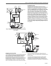
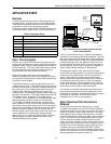
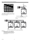
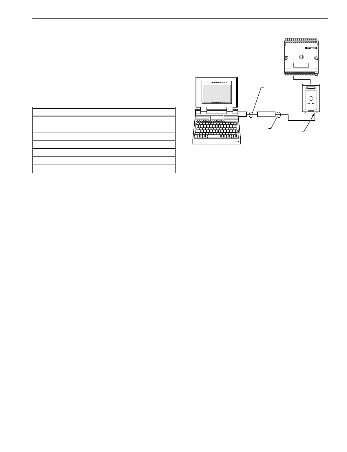
. Refer to Step 4. Prepare
Wirin
g
Dia
g
rams for details, about the about the wirin
g
differences between the two t
y
pes.
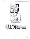
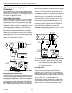
Fig. 18. Connecting the portable operator terminal
to the L
ON
W
ORKS
®
Bus.
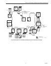
The FTT communication wirin
g
,
(
L
ON
W
ORKS
Bus
)
between
controllers is a free topolo
gy
scheme that supports T-tap, star,
loop, and mixed wirin
g
architecture. Refer to the L
ON
W
ORKS
Bus Wirin
g
Guidelines form, 74-2865 for complete description
of network topolo
gy
rules. See Application Step 3. La
y
Out
Communications and Power Wirin
g
, for more information on
bus wirin
g
la
y
out, and see Fi
g
. 27 throu
g
h 35 in Application
Step 4. Prepare Wirin
g
Dia
g
rams, for wirin
g
details.
The application en
g
ineer must review the Direct Di
g
ital
Control
(
DDC
)
j
ob re
q
uirements. This includes the Se
q
uences
of Operation for the W7750 units, and for the s
y
stem as a
whole. Usuall
y
there are variables that must be passed
between the W7750 Controllers and other zone controller
(
s
)
,
or central plant controller
(
s
)
that are re
q
uired for optimum
s
y
stem-wide operation. T
y
pical examples are the TOD Occ/
Unocc si
g
nal, the outdoor air temperature, the demand limit
control si
g
nal, and the smoke control mode si
g
nal.
It is important to understand these interrelationships earl
y
in
the
j
ob en
g
ineerin
g
process to ensure implemention when
confi
g
urin
g
the controllers.
(
See Application Step 6. Confi
g
ure
Controllers, for information on the various Excel 10
parameters and on Excel 10 point mappin
g
.
)
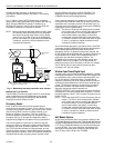
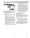
Step 2. Determine Other Bus Devices
Required
A maximum of 62 nodes can communicate on a sin
g
le
L
ON
W
ORKS
Bus se
g
ment. Each W7750
(
CVAHU
)
Controller
constitutes one node. If more nodes are re
q
uired, a Q7751A,B
Router is necessar
y
. Usin
g
a router allows up to 125 nodes,
divided between two L
ON
W
ORKS
Bus se
g
ments. The router
accounts for two of these nodes
(
one node on each side of the
router
)
; a Q7750A Excel 10 Zone Mana
g
er takes one node
and two nodes are available for operator terminal nodes,
leavin
g
120 nodes available for Excel 10 Controllers. All 120
controllers are able to talk to each other throu
g
h the router. A
Q7750A Excel 10 Zone Mana
g
er is re
q
uired to connect the
L
ON
W
ORKS
Bus to the standard EXCEL 5000
OPEN
S
y
stem C-Bus. Each Excel 10 Zone Mana
g
er supports up to
120 Excel 10 Controllers. This limit is set in the Excel 10 Zone
Mana
g
er database as an absolute maximum.
Step No. Description
1 Plan The S
y
stem
2 Determine Other Bus Devices Re
q
uired
3La
y
Out Communications and Power Wirin
g
4 Prepare Wirin
g
Dia
g
rams
5Order E
q
uipment
6Confi
g
ure Controllers
7 Troubleshootin
g
M15120A
NOTEBOOK PC
LONWORKS BUS
PORT
EIA-232
SERIAL
PORT
Q7752A
SLTA
CABLE
PART
NO. 205979
SHIELDED
INTERFACE
CABLE
EXCEL 10
W7750
CVAHU
CONTROLLER