


EXCEL 10 W7750A,B,C CONSTANT VOLUME AHU CONTROLLER
49 74-2958—1
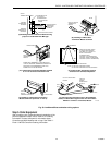
1.
Check the version numbers of the controller firmware,
E-Vision and the E-Vision script.
2.
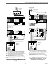
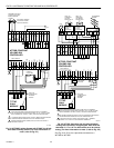
Check the wirin
g
to the power suppl
y
and make sure
there is a
g
ood earth
g
round to the controller.
3.
Check the occupanc
y
and HVAC modes.
4.
Compare the current actual setpoint with the actual
space temperature.
5.
Check the desired confi
g
uration settin
g
s.
6.
Check the network wirin
g
and t
y
pe of wire used.
7.
Check the Zone Mana
g
er mappin
g
and referred points.
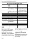
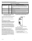
NOTE: If the fan shuts off periodicall
y
for no specific reason
and the controller restarts the fan b
y
itself after about
20 to 60 seconds, the cause could be a bad Air Flow
switch. If the controller has a di
g
ital input assi
g
ned
as a Proof of Air Flow input, tr
y
unconfi
g
urin
g
this
di
g
ital input to see if these shutdowns continue. If
not, ad
j
ust or replace the Air Flow switch to
g
et it
workin
g
.
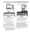
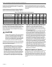
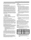
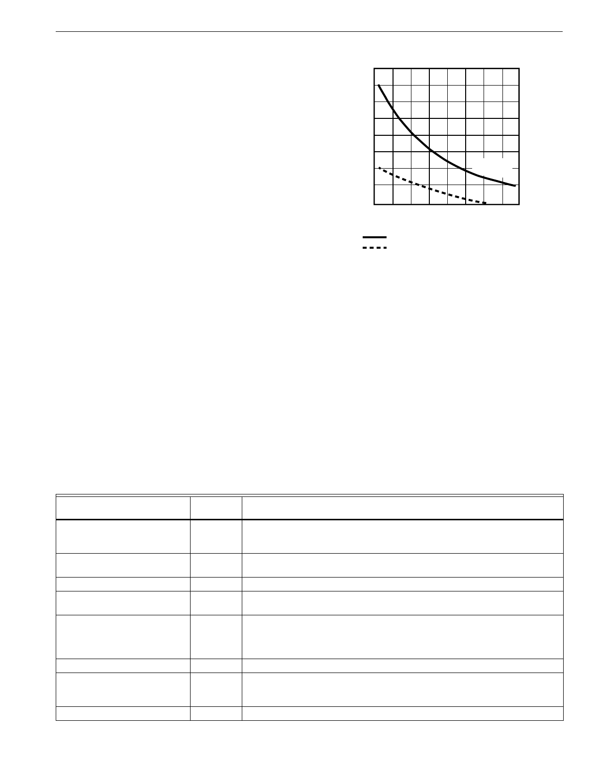
Temperature Sensor and Setpoint Potentiometer
Resistance Ranges
The T7770 or T7560A,B Wall Modules or the C7770A Air
Temperature Sensor has the followin
g
specified calibration
points, which are plotted in Fi
g
. 40:
Temperature (°F) Resistance Value (ohms)
98 11755
80 18478
70 24028
60 31525
42 52675
The T7770 Wall Module setpoint potentiometers have the
followin
g
calibration points:
Temperature (°F) Resistance Value (ohms)
85 1290
70 5500
55 9846
Fig. 40. Temperature sensor resistance plots.
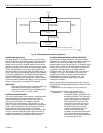
Alarms
When an Excel 10 has an alarm condition, it reports it to the
central node on the L
ON
W
ORKS
Bus
(
t
y
picall
y
, the Excel 10
Zone Mana
g
er
)
. See Table 12. Information contained in an
alarm messa
g
e is:
• Subnet Number:
L
ON
W
ORKS
Bus subnet that contains the Excel 10 node
that has the alarm condition. Subnet 1 is on the Zone
Mana
g
er side of the router; Subnet 2 is on the other
side.
• Node Number:
Excel 10 node that has the alarm condition
(
see
Network Alarm
)
.
• Alarm T
y
pe:
Specific alarm bein
g
issued. An Excel 10 can provide
the alarm t
y
pes listed in Table 12.
.
TEMPERATURE (DEGREES)
o
F
30
40 50 60 70
80
90
100
110
0
10
20
30
40
RESISTANCE (OHMS)
20K OHM AT
77
o
F (25
o
C)
80K
70K
60K
50K
40K
30K
20K
10K
o
C
M11620
AIR TEMPERATURE SENSOR
10K OHM SETPOINT POT
RESISTANCE VALUES
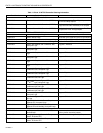
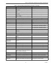
Table 12. Excel 10 Alarms.
Name of alarm or error bit
Alarm type
number Meaning of alarm code or error bit
RETURN_TO_NORMAL 128U Return to no alarm after bein
g
in an alarm condition. This code is added
numericall
y
to another alarm code to indicate that the alarm condition has
returned to normal.
ALARM_NOTIFY_DISABLED 255U The alarm reportin
g
was turned off b
y
DestManMode. No more alarms are
reported until DestManMode turns on alarm reportin
g
or on application restart.
NO_ALARM 0 No alarms presentl
y
detected.
INPUT_NV_FAILURE 1 One or more NV inputs have failed in receivin
g
an update within their specified
FAILURE_DETECT_TIME.
NODE_DISABLED 2 The control al
g
orithm has stopped because the controller is in
DISABLED_MODE, MANUAL or FACTORY_TEST mode. No more alarms are
reported when the controller is in the DISABLED_MODE. Alarms continue to be
reported if the controller is in the MANUAL or FACTORY_TEST mode.
SENSOR_FAILURE 3 One or more sensors have failed.
FROST_PROTECTION_ALARM 4 The space temperature is below the frost alarm limit 42.8°F
(
6°C
)
when the
mode is FREEZE_PROTECT. The alarm condition remains until the temperature
exceeds the alarm limit plus h
y
sterisis.
INVALID_SET_POINT 5 One of the setpoints is not in the valid ran
g
e.