


EXCEL 10 W7750A,B,C CONSTANT VOLUME AHU CONTROLLER
74-2958—132
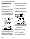
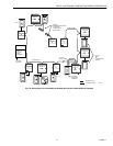
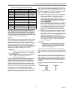
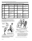
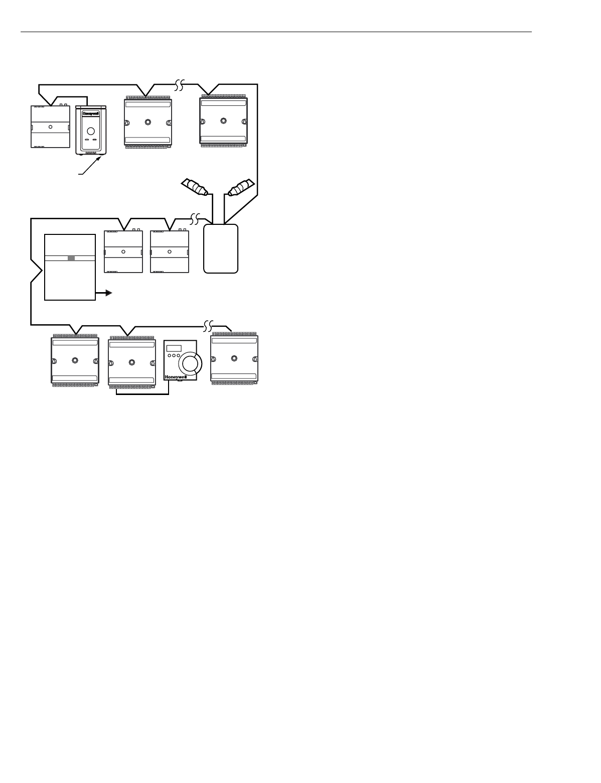
Fig. 20. Wiring layout for two singly terminated
L
ON
W
ORKS
®
Bus segments.
NOTE: See the L
ON
W
ORKS
Bus Termination Module section
for wirin
g
details.
IMPORTANT
Notes on communications wiring:
• All field wiring must conform to local codes and ordi-
nances or as specified on installation wiring dia-
grams.
• Approved cable types for L
ON
W
ORKS
Bus communi-
cations wiring is Level IV 22 AWG (0.34 mm
2
) ple-
num or non-plenum rated unshielded, twisted pair,
solid conductor wire. For nonplenum areas, use
Level IV 22 AWG (0.34 mm
2
), such as U.S. part
AK3781 (one pair) or U.S. part AK3782 (two pair). In
plenum areas, use plenum-rated Level IV, 22 AWG
(0.34 mm
2
) such as U.S. part AK3791 (one pair) or
U.S. part AK3792 (two pair). See Tables 9 and 11 for
part numbers. Contact Echelon Corp. Technical Sup-
port for the recommended vendors of Echelon
approved cables.
• Unswitched 24 Vac power wiring can be run in the
same conduit as the L
ON
W
ORKS
Bus cable.
• Do not use different wire types or gauges on the
same L
ON
W
ORKS
Bus segment. The step change in
line impedance characteristics causes unpredictable
reflections on the bus. When using different types is
unavoidable, use a Q7751A,B Router at the junction.
• In noisy (high EMI) environments, avoid wire runs
parallel to noisy power cables, or lines containing
lighting dimmer switches, and keep at least 3 in.
(76 mm) of separation between noisy lines and the
L
ON
W
ORKS
Bus cable.
• Make sure that neither of the L
ON
W
ORKS
Bus wires
is grounded.
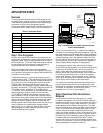
Power Wiring
A power bud
g
et must be calculated for each Excel 10 W7750
Controller to determine the re
q
uired transformer size for
proper operation. A power bud
g
et is simpl
y
the summin
g
of
the maximum power draw ratin
g
s
(
in VA
)
of all the devices to
be controlled b
y
an Excel 10 W7750 Controller. This includes
the controller itself, the e
q
uipment actuators
(
ML6161, or
other motors
)
and various contactors and transducers, as
appropriate, for the Excel 10 confi
g
uration.
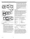
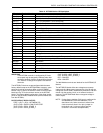
POWER BUDGET CALCULATION EXAMPLE
The followin
g
is an example power bud
g
et calculation for a
t
y
pical Excel 10 W7750B Controller.
Assume a W7750 unit with a fan, two sta
g
es of D/X coolin
g
,
modulatin
g
steam valve for heatin
g
, and modulatin
g
economizer dampers. The power re
q
uirements are:
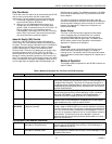
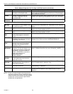
DeviceVA Information Obtained from
Excel 10 W7750B,C 12.0 W7750 Specification Data
Controller
ML6161 2.2 TRADELINE
Damper Actuator Catalo
g
R8242A 21.0 TRADELINE
Contactor for fan Catalo
g
in-rush ratin
g
D/X Sta
g
es 0.0
NOTE: For this example, assume the coolin
g
sta
g
e outputs
are wired into a compressor control circuit and,
therefore, have no impact on the power bud
g
et.
)
M6410A Steam 0.7 TRADELINE
Heatin
g
Coil Valve Catalo
g
, 0.32A at 24 Vac
TOTAL: 35.9 VA
The Excel 10 S
y
stem example re
q
uires 35.9 VA of peak
power; therefore, a 40 VA AT72D Transformer is able to
provide ample power for this controller and its accessories.
Alternativel
y
, a 75 VA AT88A Transformer could be used to
power two Excel 10 S
y
stems of this t
y
pe, or a 100 VA AT92A
Transformer could be used to power two of these Excel 10
S
y
stems and meet NEC Class 2 restrictions
(
no
g
reater than
100 VA
)
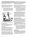
. See Fi
g
. 22 and 23 for illustrations of power wirin
g
details. See Table 8 for VA ratin
g
s of various devices.
EXCEL 10
VAV
EXCEL 10
VAV
EXCEL 10
VAV
EXCEL 10
Q7750A
ZONE
MANAGER
TO C-BUS
(SEE FIG. 1)
L
ONWORKS BUS
SEGMENT NUMBER 2
L
ONWORKS BUS
SEGMENT NUMBER 1
L
ONWORKS BUS
SEGMENT NUMBER 2
T7770
L
ONWORKS
BUS
ACCESS
Q7751A
FTT
L
ONWORKS
BUS
ROUTER
209541B
TERMINATION
MODULE
209541B
TERMINATION
MODULE
M17497
EXCEL 10
CVAHU
EXCEL 10
CVAHU
EXCEL 10
CVAHU
EXCEL 10
CVAHU
EXCEL 10
CVAHU
T7560A,B