EXCEL 10 W7750A,B,C CONSTANT VOLUME AHU CONTROLLER
74-2958—166
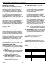
All of the NvName values that are stored in EEPROM memor
y
have a prefix of
nci
.
NOTE: These parameters are stored in EEPROM and are
limited to 10,000
writes
. Do NOT use them as
outputs from Control Strate
g
ies,Time Pro
g
rams, or
Switchin
g
Tables. If these points are chan
g
ed more
than 10,000 times, irreversible hardware failure
results
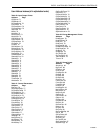
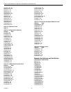
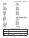
Tables 20 throu
g
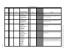
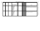
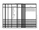
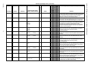
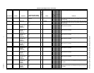
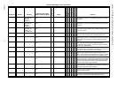
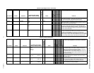
h 28 provide point attributes as follows:
En
g
ineerin
g
Units— This field indicates the point valid ran
g
e and
displa
y
ed En
g
ineerin
g
Unit. For di
g
ital points,
the valid states and the correspondin
g
enumerated values are shown.
Default— The value or state of the point on controller
start-up.
E-Vision
(
M
)
Monitor— These points are viewable within the E-Vision
Controller Monitorin
g
on-line screen.
(
P
)
Parameter—These points refer to control parameters
settable in the Application Selection dialo
g
boxes in E-Vision.
(
S
)
Schematic—These points appear in E-Vision monitor
mode
g
raphics.
Shareable— These points can be set up for data sharin
g
in
Command Multiple Points, Read Multiple
Points, or Refer Excel 10 Points as either a
data source or a destination.
Mappable— These points can be converted into a C-Bus
point used b
y
C-Bus devices. A mappable point
has a one-to-one relationship with a C-Bus
User Address.
Direct
Access— These points are accessible throu
g
h the
Subs
y
stem Points mechanism in XBS.
Hardware
Confi
g
.— These are points that involve controller I/O
confi
g
uration. An
y
chan
g
e to Hardware Confi
g
.
points causes the W7750 to perform an
application reset; therefore, these points can
onl
y
be modified off-line.
Manual
Confi
g
.— These points are used to set the controller
outputs when in manual mode. The W7750 is
placed in manual mode throu
g
h a menu
selection in the E-Vision Controller Monitor
screen.
Test— These points can be controlled in E-Visions test
mode that is used for field checkout/ debu
g
in
g
.
Failure Detect
Input Point— These points need an update periodicall
y
or a
communication alarm is
g
enerated. The failure
detect mechanism is onl
y
active when the NV is
bound
(
bindin
g
s are confi
g
ured usin
g
Refer
Excel 10 points
)
. The time between the updates
is user settable.
Non-Failure Detect
Input Point— These points
(
which are NVs that are bound or
unbound
)
do not check for an update
periodicall
y
and do not
g
enerate an alarm.
NOTES:
1. Mapped points can be viewed and chan
g
ed,
if
needed
, on the XI581, XI582 and XI584 C-Bus
devices and on an XBS central and on E-Vision.
2. All Excel 10 points, mappable and calibration,
confi
g
uration and internal data sharin
g
points, can
be viewed and chan
g
ed,
as allowed
, via Direct
Access
(
DA
)
mode in the XBS subs
y
stem menu
or via XI584.


