


Blank Front Panel Option 001 81
Use format appropriate for your computer.):
10 OUTPUT 705; “VOUT?”
20 ENTER 705; A$ 30 OUTPUT 705; “OVP?”
40 ENTER 705; B$
50 DISP A$,B$
60 GOTO 10
70 END
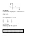
Turn OVP ADJUST potentiometer counterclockwise while observing VOUT and OVP readings on computer display.
VOUT should drop to about 0 volts as OVP is adjusted below 10 volts. Stop program. Send string:
STS?
And address the power supply to talk. The response should be:
STS 8
indicating that the OVP circuit has tripped. Turn OVP ADJUST potentiometer fully clockwise. Send String:
RST
Restart program. VOUT should read 10 volts. Stop program.
c. To check constant current circuit, turn power supply off and connect a wire capable of handling the full current of the
power supply across + and - terminals on rear panel.
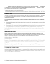
d. Turn power supply on and send the appropriate string in Table B-2.
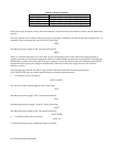
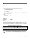
Table B-2. CC Check Command String
Agilent Model String
Agilent 6030A ISET 17 VSET 2
Agilent 6031A ISET 120 VSET.2
Agilent 6032A ISET 50 VSET.6
Agilent 6033A ISET 30 VSET.2
Agilent 6035A ISET 5 VSET 5
Agilent 6038A ISET 10 VSET.6
Wait one second for power supply to settle. Send string:
STS?
and address the power supply to talk. The response should be:
STS 2
indicating that power supply is in the CC mode. Send string:
IOUT?
and address the power supply to talk. The response should be: the ISET value set in step d. above.
e. Turn off power supply, remove short from output, and read remainder of Section 3, except for LOCAL OPERATION,
before connecting load to supply.
Overvoltage Protection Setting
For ease in setting the OVP trip voltage, use a looping program such as that listed in the check out procedure. This enables
you to read the OVP trip voltage on the computer display while adjusting OVP at the power supply front panel.