


Installation
25
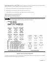
b. Use a small-blade screwdriver to set the two switch sections of S2 to match the pattern silk-screened on main board for
nominal line voltage to be used. For example, to set switches for 120 V operation, move forward switch section so that
its white slot is toward front of supply and move rearward switch section so that its white slot is toward rear of the
instrument.
c. Set switch S1 to match the rearward section of S2, i.e., toward the rear for 100/120 V operation, toward the front for
220/240 V operation.
d. One end of W1 is soldered to the main board; the other end has a female quick-connect terminal that fits onto one of
two terminals soldered to the main board. For 100 V or 120 V operation, W1 must be connected to terminal J9; for 220
V or 240 V operation, W1 must be connected to terminal J10. Be certain that jumper is firmly mated with connector on
main board. Do not grip jumper insulation with pliers; either grip jumper wire by hand or grip jumper terminal with
pliers.
e. Replace the inside top cover and the outside top cover. Mark the unit clearly with a tag or label indicating correct line
voltage to be used.
f. Change line label.
Agilent Models 6033A, Agilent 6038A. Line voltage conversion is accomplished via three components; a two-section line
select switch, line voltage jumper, and a rear panel fuse.
To convert the supply from one voltage to another, proceed as follows:
a. Remove the outside cover by removing the rear screw that holds the carrying strap, then carefully slide the cover to the
rear of the supply until it is clear.
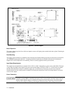
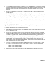
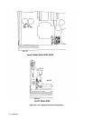
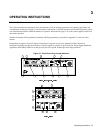
b. The line voltage select switch (S2) is located in the front left corner of the supply (see Figure 2-3). Use a small-blade
screwdriver to set the two switch sections to match the pattern silk-screened on p.c. main board as shown in Figure 2-3.
For example, to set switches for 120 V operation (as illustrated), move forward switch section so that its white slot is
toward front of supply and move rearward switch section so its white slot is toward rear of supply.
c. One end of W5 is soldered to motherboard; the other end has a female right-angle quick-connect terminal that fits onto
one of two terminals soldered to motherboard. For 100 V or 120 V operation, W5 must be connected to terminal closer
to center of supply; for 220 V or 240 V operation, W5 must be connected to terminal closer to side of supply. Be
certain that jumper is firmly mated with terminal on motherboard. Do not grip jumper insulation with pliers; either grip
jumper wire by hand or grip jumper terminal with pliers.
d. Check rating of fuse installed in rear-panel fuseholder. It should be 8 A for 100 or 120 Vac line voltages, or 4 A for
220 or 240 Vac line voltages. If necessary, replace the fuse with one of correct value. Do not use time-delay fuses.
8 AM fuse, Agilent part number 2110-0383
4 AM fuse, Agilent part number 2110-0055
e. Replace covers and mark the supply clearly with a tag or label indicated correct line voltage and fuse to be used.