


Operating Instructions
34
Once the all-indicators-off period is over, the GP-IB address switch setting is displayed on the meter displays for one
second. For example, if the address switches were set for address 5, the display would be: Adr 5
If the unit fails any of the self tests an error code is displayed on the meter displays. The unit will not respond to any
commands, either from the front panel or GP-IB, and it should be removed for service. See the Service manual for a listing
of the self test failure codes.
NOTE Because the power supply is testing itself, it is not possible to guarantee that the unit will provide an
unambiguous indication of all possible failures. For example, a failure in the core of the microcomputer or
in the hardware used to light the front-panel display may prevent the unit from indicating that it has failed
a test.
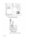
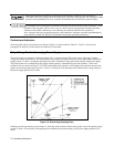
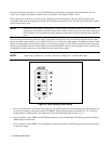
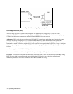
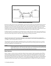
The following procedure ensures that the supply is operational, and may be used as an incoming inspection check. Ensure
that the rear-panel mode switches are set as shown in Figure 3-4, and that the sensing jumpers are tightened securely. Check
that the rear-panel label indicates that the supply is set for the line voltage to be used. There should be no cables connected
to the rear panel GP-IB connector. Check that the recessed OVP ADJUST control on the front panel is fully clockwise. The
GP-IB address switches may be set to any address from 0 to 30 for this procedure.
NOTE +Sense lead is jumpered to + out and - sense lead is jumpered to - out lead at the factory.
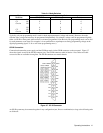
Figure 3-4. Factory Settings, Mode Switch
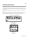
a. Press top of LINE rocker switch in to turn supply on. Fan should operate. Check that display shows GP-IB address set
by rear-panel switches. After address display, CURRENT indicator should remain on and either CV or CC indicator
should remain on. (SRQ indicator will remain on if rear-panel PON SRQ switch has been set to 1.)
b. Press momentary-contact DISPLAY SETTINGS pushbutton switch and check that VOLTS display indicates 0.00 and
AMPS display indicates 0.00.
c. Press momentary-contact DISPLAY OVP pushbutton switch and check that VOLTS display indicates maximum OVP
for the power supply.