


Operating Instructions
33
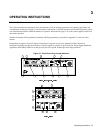
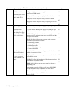
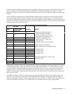
Table 3-1. Controls and Indicators (continued)
Number Controls/Indicators Description Page
5 Numeric Display Two 3-1/2 digit alphanumeric displays with automatically
positioned decimal point that ordinarily indicate output VOLTS
and AMPS (see items 6 & 7). When power supply is turned on all
segments light for approximately 1 second. During an error
condition, power supply output may exceed display range; displays
will indicate + OL or - OL.
33
6 DISPLAYS SETTINGS
Pushbutton Switch
Causes numeric displays to indicate programmed voltage and
current values, rather than actual output values; allows both settings
to be made without the necessity of opening or shorting load.
35
7 DISPLAY OVP
Pushbutton Switch
Causes VOLTS display to indicate OVP trip voltage, AMPS
display is blanked; allows setting to be made without changing
output settings or load connections.
38
8 OUTPUT ADJUST
Controls - Rotary Pulse
Generator (RPG) and
pushbutton switch
OUTPUT ADJUST knob functions either as a voltage control or a
current control, as determined by the pushbutton switch and
indicated by whichever (green) indicator, VOLTAGE or
CURRENT, is on. Knob functions as a two-speed device; faster
rotation causes greater rate of change per revolution. OUTPUT
ADJUST controls operate only when unit is under local control.
38
9 FOLDBACK Control The pushbutton switch toggles foldback protection on and off in
local operation; has no effect if power supply is not in CV or CC
(ERROR LED flashes), or is in remote. Switch also resets foldback
protection circuit if it has disabled power supply output.
FOLDBACK ENABLED LED (green) operates in either local or
remote.
39
10 OVP ADJUST The recessed, single-turn screwdriver control sets the overvoltage
protection trip voltage.
43
11 LINE Switch Turns ac power on and off. 34
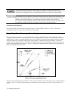
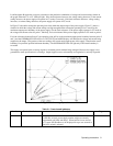
NOTE Under certain conditions of line and load, it is possible for the supply to provide more than rated output
power and still maintain regulation. If this occurs, the unit will operate normally and the OVERRANGE
indicator will be off. However, the slightest change in either line or load may cause the unit to go out of
regulation. Operation of the unit beyond the rated-output-power boundary is not recommended under any
circumstances.
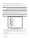
Turn-On Checkout Procedure
The power supply performs a series of self tests each time power is turned on. All front-panel LEDs, including all meter
segments, are also turned on. The tests take approximately one second to complete, and all indicators remain on while the
tests are running. This alerts the operator that self tests are running, and allows the operator to note if any indicators are
inoperative.
After the self tests are completed all front-panel indicators are turned off for one-half second, allowing the operator to note
if any are stuck on. If the operator suspects that any indicator may be malfunctioning he should turn power off and back on
again while observing that indicator.