


Operating Instructions
45
Multiline Message Control Functions. The Acceptor Handshake, Source Handshake, Listener, and Talker functions are
implemented by the interface circuits of the power supply and the controller and require no action by the user. The LSN or
TLK indicators turn on when the power supply is addressed to listen or talk. (The talker function includes serial poll, see
below).
Service Request. Service request is a uniline message that can be asserted by the power supply to interrupt the controller.
Service request can be generated by a power supply fault condition. The operator defines which of eight power supply
conditions are defined as faults. Enabling or disabling a condition from asserting service request does not affect the
condition within the power supply, nor does it affect the front-panel status indicators. Page 62 provides instructions for
unmasking service request capability.
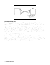
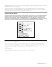
A service request can also be generated at power on (PON), depending on the setting of the rear-panel PON SRQ switch.
Therefore, with PON SRQ enabled, if a momentary power dropout causes the power supply memory to lose its programmed
values, PON alerts the operator that the power supply has been initialized (see Page 47).
If the power supply fails self test at power on it will not respond to serial poll or any other commands on GP-IB. The user
should include a time-out in his program after which the controller will not wait for the power supply to respond. If the time-
out occurs, the power supply can be assumed to be malfunctioning and should be removed for service.
The SRQ indicator turns on whenever the power supply is requesting service from the controller, and remains on until the
controller conducts a serial poll. Serial poll resets the SRQ bit and turns off the SRQ indicator, regardless of whether the
fault that caused service request continues to exist.
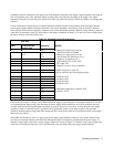
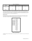
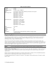
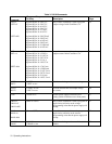
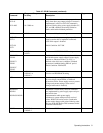
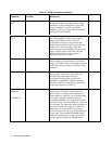
Serial Poll. In a serial poll the controller can poll each device on the bus, one at a time. The power supply responds by
placing the contents of the eight-bit serial poll register on the GP-IB data lines. Table 3-5 defines each of the bits in the
serial poll register and defines what causes each bit to be set and reset. Bit positions 0 through 7 are placed on DIO lines 1
through 8. Note that the serial poll register represents only the power supply connected to the GP-IB, not other power
supplies that may be slaved to the GP-IB connected unit.
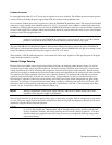
Parallel Poll. Parallel poll allows the controller to receive one bit of data from each of many or all instruments on the bus at
the same time. In Agilent Technologies power supplies this bit corresponds to bit 6, the RQS bit, of the serial poll register.
Because the controller can receive this bit from at least eight instruments at one time, the controller can determine quickly
which of a number of instruments on the bus requested service. The controller can then query that instrument to determine
the cause of the service request. Parallel poll does not reset the service request bit in the power supply. The power supply’s
response to parallel poll can be configured remotely from the controller, or it can be configured locally.
Unless configured remotely, the power supply responds to a parallel poll with a "1" on one of the DIO lines (if requesting
service), as determined by the setting of its address switches. Addresses 0 through 7 correspond to DIO lines 1 through 8
(decimal weight 2
0
through 2
7
). If the address switches are set to 8 or higher, the power supply will not respond to a parallel
poll unless the unit is configured remotely. The power supply can not return a "0" to indicate it was requesting service
unless it has been configured remotely.
The power supply can be configured remotely to respond to a parallel poll with either a ’’1’’ or a ’’0’’ on one of the DIO lines
if the unit is requesting service. Configuration statements with a decimal value of 0 through 7 will configure the unit to
respond with a "0" on one of the DIO lines 1 through 8; decimal values of 8 through 15 configure the unit to respond with a
"1" on one of DIO lines 1 through 8. By configuring the power supply remotely, the address switches may be set to any
address from 0 through 30 without affecting the parallel poll response. The capability to configure either a "0" or "1"
response allows the user to AND or OR two or more instruments on one DIO line.