


Operating Instructions
40
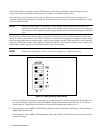
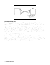
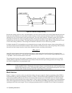
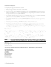
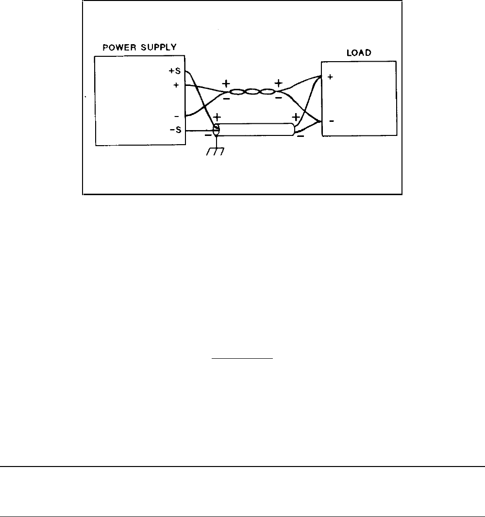
Figure 3-6. Remote Voltage Sensing
Because the sensing leads carry only a few milliamperes, the wires used for sensing can be much lighter than the load leads.
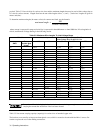
Each sense lead should have no more than 0.2 ohms resistance. Use the resistivity columns in Table 3-2 to determine the
minimum wire size for the length of sense leads being used. The sense leads should be a shielded, twisted pair to minimize
the pickup of external noise. Any noise picked up on the sensing leads will appear at the supply’s output, and CV load
regulation may be adversely affected. The shield should be grounded at the power supply end only, and should not be used
as one of the sensing conductors. The sensing leads should be connected as close to the load as possible.
If slightly degraded CV load regulation can be tolerated, the power supply will provide remote voltage sensing with up to 2
Vdc drop in each load lead and with more than 0.2 ohms resistance in each sense lead. As the voltage drop in the load leads
increases, the load voltage error due to sense-lead resistance increases according to the formula:
(2Rs +.5) V1
1000
where Rs is the resistance in ohms of each sense lead and Vl is the voltage drop in each load lead. For example, if the
resistance in each sense lead is 1 ohm and the voltage drop in each load lead is 2 Vdc, the load voltage might differ by [2(1)
+.5]2/1000 = 5 mVdc from that with no sense-lead.
The sensing leads are part of the supply’s programming circuits, so they should be connected in such a way as to make it
unlikely that they might inadvertently become open circuited. If the sense leads open during operation, the voltage at the
load will rise slightly above its programmed value.
NOTE The power supply includes protection resistors which reduce the effect of open sense leads during remote-
sensing operation. If the + S lead opens, the output voltage is sensed between the + OUT terminal and the
negative side of the load. If the - S lead opens the output voltage is sensed between the positive side of the
load and - OUT. If both sense leads open, the output voltage is sensed locally.
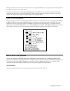
Mode Switches
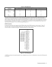
Figure 3-4 shows six switches on the rear panel that configure the power supply for digital programming (either GP-IB or
front-panel RPG) or analog programming (resistance or voltage). (Note that front panel programming is digital; the rotary
pulse generator (RPG) produces pulses that are monitored by the microprocessor, which then raises or lowers the digital
input to the DACs that control the power supply output.) Table 3-4 shows the proper switch settings for each programming
mode. When shipped from the factory the switches are set for GP-IB/front-panel-RPG programming, which is the normal
operating mode for this power supply. The two analog programming modes are available for use in special circumstances.