


Installation
24
d. Replace the cover, tighten all four screws and tighten the strain relief clamp. (All four screws must be tightened for unit
to meet RFI specifications.)
e. Connect the other end of the power cord to an appropriate power source.
Note Connections to the ac power line must be made in accordance with applicable electrical codes. The
international color code for identifying mains supply conductors is green/yellow, blue, and brown for
earth, neutral, and line respectively. Corresponding USA/Canadian codes are green, white, and black.
Before applying power to the instrument, check to see that the rear-panel circuit breaker CB1 is on
(breaker may trip because of rough handling during transit). If the breaker trips while power is on, or
if the breaker is found to be tripped at any time for unknown reasons, refer to troubleshooting
procedures in the Service Manual.
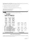
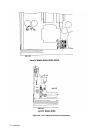
Agilent Models 6033A, 6038A. The power supply is shipped from the factory with a power-cord plug appropriate for the
user’s location. Figure 2-2 illustrates the standard configuration of power-cord plugs used by Agilent Technologies. With
each drawing is the Agilent Part Number for a replacement power cord equipped with a plug of that configuration. If a
different power cord is required, contact the nearest Agilent Technologies Sales and Service office.
To protect operating personnel, the National Electrical Manufacturers Association (NEMA) recommends that the instrument
panel and cabinet be grounded. This supply is equipped with a three-conductor power cable; the third conductor is the
ground conductor. When the cable is plugged into an appropriate receptacle the supply is grounded. In no event shall this
supply be operated without an adequate cabinet ground connection.
The offset pin on the standard power cable three-prong connector is the ground connection. If a two-contact receptacle is
encountered, it must be replaced with a properly grounded three-contact receptacle in accordance with the National
Electrical Code, local codes and ordinances. The work should be done by a qualified electrician.
Note Generally, it is good practice to keep the ac input lines separated from signal lines.
Line Voltage Option Conversion
Conversion to or from 100 V operation requires recalibration and replacement of internal components
in addition to the line voltage components, and is to be done only at the factory. Failure to reconfigure
and recalibrate the power supply may result in damage to the unit.
Agilent Models 6030A, 6031A, 6032A, 6035A. Line voltage conversion is accomplished by adjusting three components:
a two-section line select switch, and a line-voltage jumper. To convert the supply from one line voltage option to another,
proceed as follows:
Some components and circuits are at ac line voltage even with the LINE switch off. To avoid electric
shock hazard, disconnect line cord and load, and wait two minutes before removing cover.
a. Remove the outside cover by removing the four screws that hold the carrying straps, spread the bottom of the cover
slightly and carefully slide the cover to the rear of the supply until it is clear. Next remove the top inside cover by
removing the nine screws, four on top, three on right side, and two on left side, which connect the top inside cover to
the supply chassis.