


Operating Instructions
69
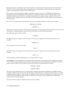
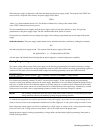
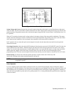
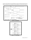
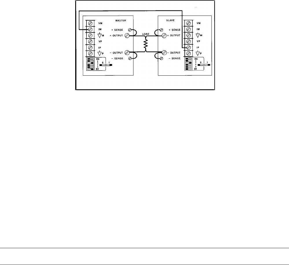
Figure 3-14. Auto-Parallel Operation
Setting Voltage and Current
. Program the slave unit’s output voltage above the master’s to avoid interference with master-
unit CV control. The slave unit’s mode switches disable the slave unit’s digital current setting from having any effect in auto-
parallel operation. Program the master unit to the desired output voltage and 50% of total current. Verify that the slave is in
CC operation.
When in CV operation, the master unit’s voltage setting is the output voltage of the auto-parallel combination. The output
current is the total current from all units. The fraction of total current that each unit provides is the same as the ratio of that
unit’s output current capability to the total output current capability of the auto-parallel combination.
In CC operation, the user must add up the current outputs from each unit and adjust the master until the total equals the
desired load current.
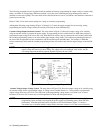
Overvoltage Protection. Adjust the desired OVP shutdown limit using the master unit’s OVP ADJUST control. Set the slave
unit’s OVP limit above the master’s. When the master unit shuts down, the master programs the slave unit to zero voltage
output. If a slave unit shuts down (because its OVP shutdown limit is set lower than the master’s), it shuts down only itself,
and the other unit supplies all the load current. The shut-down slave unit will draw some current through its down
programming circuit. The extra current required from the master unit may cause the master to switch from CV to CC mode.
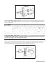
Remote Sensing. To remote sense with auto-parallel operation, connect remote-sense leads only to the
master unit according to the remote-sensing instructions on Page 39.
NOTE Down-programming speed is slower with auto-parallel operation because only the master unit’s down
programmer operates.
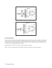
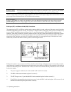
Series Operation
Up to two supplies can have their outputs connected in series to provide increased output voltage. Each power supply is
programmed via GP-IB with hold on, and then all units are triggered at once. Multiple loads may be connected in series, and
the combination may be grounded at any one point to provide both positive and negative outputs. Regardless of whether or
where the load is grounded, no point may be at a greater potential (+ or-) from ground than that specified on the output label
on the rear chassis.