


Operating Instructions
70
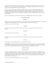
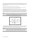
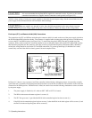
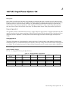
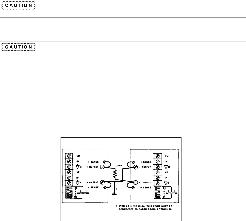
It is not recommended that Agilent 6035A supplies be connected in series. if you do so, the common
connection between the two supplies must be connected to earth ground (see Figure 3-15).
Add the voltage settings of each power supply together to determine the total output voltage. Set the current limits for each
power supply to the maximum that the load can handle without damage.
When two supplies are operated in series, they should be programmed to the same voltage to prevent
possible damage to the lower voltage supply during short circuit conditions. Contact the factory if this is not possible.
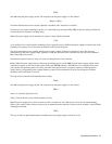
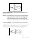
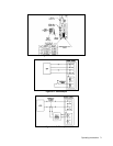
Fault Input (FLT) and Remote Inhibit (INH) Connections
The connections for FLT and INH are made through a connector which is located on the rear of the power supply just below
the GP-IB address/PON selection switches. The connector is supplied with its mating plug which provides a convenient way
to access the FLT and INH circuitry (see Figure 3-16). To remove the plug grip it firmly, then pull it straight out of the
connector. With a small screwdriver, loosen the terminal screws on the plug; connect the external FLT and/or INH circuitry,
then install the plug back into the connector. Note that in order to prevent radio frequency interference (RFI), shielded or
twisted pair wiring should be used for the FLT and INH connections. To prevent ground loops (if shielded wire is used)
connect only one end of the shield to chassis ground. Several examples follow.
Figure 3-15. Series Operation
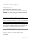
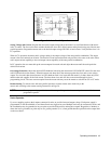
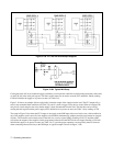
In Figure 3-17 shows a way to protect a load if the controller is halted during a debugging session. An externally, normally
open switch (S1) is mounted on a hinged protection hood which covers the device under test. The terminals of the switch are
connected to the INH input line. When the hood is lifted, the switch closes and the following simultaneous actions are taken
by the power supply:
1. The power supply is disabled (as it is when an OUT OFF or OUT 0 is issued).
2. The RI bit in the status and astatus registers is set true (1).
3. The FLT line goes true (1) (provided the RI bit in the unmasked register has been set true (1)).
4. If the RI bit in the unmasked register has been set true (1) then the RI bit in the fault register will be set true (1) and
the FAU bit in the serial poll register will be set true (1).