


Programming the Agilent 603xA Power Supplies Using Basic
115
D
Programming the Agilent 603xA Power Supplies Using
Basic
Introduction
The examples in this appendix are provided as an introduction to programming the Agilent 603xA power supplies with
HPSeries 200/300 controllers using the BASIC programming language. The programming examples explain some of the
more frequently used programmable functions of the power supplies.
NOTE: The examples in this appendix use the original language commands (ARPS) as described in section III of
this manual.
The Agilent 603xA supplies can also be programmed using the SCPI commands as described in appendix C. In most cases,
you can use the programming examples in this appendix with the SCPI commands. Simply replace the ARPS command
string in the examples with the corresponding SCPI command string (see table C-6).
For more information about programming with BASIC, refer to the documentation provided with the HP Series 200 or 300
controller.
I/O Path Names
Throughout this appendix, I/O path names are used in place of interface and device select codes. In a large program, I/O
path names simplify changing the address of an instrument if it becomes necessary. Reading and writing of the program are
easier as well. The I/O path name can be carried in a common block and changed by a single assign statement.
In the following programming examples, the I/O path name @PS is used for the power supply. Note that the statement:
OUTPUT 705; "VSET 5"
is equivalent to:
OUTPUT @PS; "VSET 5”
as long as an assign statement defining the I/O path name @PS precedes any statements using the I/O path name.
Initialization
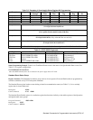
Sending the power supply the device command “CLR” will return the supply to its turn-on state. This function is useful for
initialization to a known state within a program. Table 3-6 contains a list of the initial conditions.
Voltage and Current Programming
The power supply normally functions in one of two modes, either constant voltage with current limit or constant current
with voltage limit. The operating mode is set by a combination of the set values and the load. For example, if the supply
does not have a load connected, the following statements will put the supply in constant voltage mode at 5 volts out with a
10 amp current limit:
OUTPUT @PS;"VSET 5;ISET l0"
or OUTPUT @PS;"VSET";5;" ;ISET";l0