


Operating Instructions
31
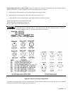
Load Resistance B equals the crossover resistance for the particular combination of voltage and current settings shown on
the graph. Either the CV or CC LED will light. If the load resistance increases, the voltage setting decreases, or the current
setting increases, the power supply will operate in CV mode. Conversely, if the load resistance decreases, voltage setting
increases, or current setting decreases, the power supply will operate in CC mode.
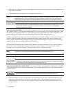
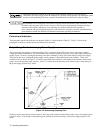
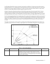
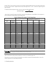
In Figure 3-2 the entire rectangular operating locus falls within the output range of the power supply. Figure 3-3 shows a
situation in which the voltage and current settings are high enough that the rectangular operating locus is cut off by the
maximum output power boundary of the power supply. For the load resistance A, the power supply operates in CV mode at
the voltage and current values for point 1. Similarly, for load resistance D the power supply operates in CC mode at point 4.
For load resistances between B and C, the operating point will be on the maximum output-power boundary between points 2
and 3, and the OVERRANGE LED will be on. The VOLTS and AMPS displays will indicate the voltage and current being
supplied to the output. (The product of the two readings will exceed rated output power of the supply.) Note that the actual
boundary is beyond the specified minimum boundary. The OVERRANGE LED will light only if the actual boundary is
exceeded.
The supply can operate in the overrange region for sustained periods without being damaged. However, the supply is not
guaranteed to meet specifications in overrange. Output ripple increases substantially and regulation is seriously degraded.
Figure 3-3. Overrange Operation
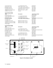
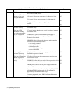
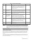
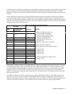
Table 3-1. Controls and Indicators
Number Controls/Indicators Description Page
1 LCL Pushbutton Returns unit to local control (unless local lockout has been received
via GP-IB). In local, power supply remains subject to remotely
programmed soft limits and delays. When held in for one second,
LCL causes GP-IB address to be displayed for up to two seconds or
until LCL switch is released.
44