


Blank Front Panel Option 001 79
B
Blank Front Panel Option 001
Introduction
This appendix describes the blank front panel option (Option 001) for the power supply. Option 001 is designed for
applications in which front panel operation and monitoring are unnecessary. It has no front-panel controls and indicators
except for the LINE switch and OVP ADJUST control found on the standard unit, and a pilot light to indicate when ac input
power is turned on. All other characteristics of the standard power supply are retained.
Except for references to front-panel controls and indicators, most of the information in the manual applies to Option-001
units. No attempt has been made in this appendix to change every reference to the front-panel controls and indicators. In
general, information in this appendix replaces only those procedures whose modification may not be obvious to the user.
When reading the manual, the user can usually skip over references to front panel controls and indicators other than the
LINE switch and OVP ADJUST control.
Description
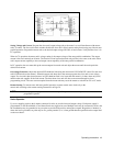
The front panel printed-circuit assembly of the standard unit is not used in the Option-001 unit. Instead, the LINE switch,
pilot light, and 10-turn OVP ADJUST potentiometer are mounted directly to the front chassis. Cables from the pilot light
and the OVP ADJUST potentiometer plug onto the control board. Wires from the main board plug onto the back of the
LINE switch.
Turn-On Check Out Procedure
The following procedure ensures that the unit is operational, and may be used as an incoming inspection check.
You should know how to operate the computer and send commands over the GP-IB. Read pages 44 through 65 to
familiarize yourself with GP-IB control of the power supply; pay particular attention to the description of programming
syntax (starting on page 48). Table 3-7 provides a summary of each of the GP-IB commands.
Refer to the Introductory Operating Guide specified in Section I for programming examples you can use to familiarize
yourself with the power supply and its capabilities.
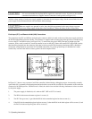
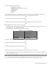
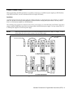
Before starting this procedure, ensure that the rear panel mode switches are set as shown in Figure 3-4, and that the sensing
jumpers are tightened securely. Check that the rear-panel label indicates that the unit is set for the line voltage to be used.
Check that the recessed OVP ADJUST control on the front panel is fully clockwise. Connect GP-IB cable from computer to
rear-panel GP-IB connector.
The power supply performs a series of self tests each time power is turned On. The tests take approximately one second to
complete. If the unit fails any of the self tests it will not respond to any commands from the GP-IB, and it should be
removed for service.
NOTE Because the power supply is testing itself, it is not possible to guarantee that the unit will find every
possible failure.
a. Press top of LINE rocker switch to turn unit on. Pilot light should turn on, and fan should operate.
b. Send string:
ID?
and address the power supply to talk. The response should be shown in Table B-1.