


Operating Instructions
41
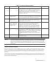
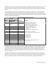
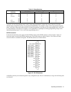
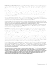
Table 3-4. Mode Switches
Mode Programming Mode
Switches GP-IB/RPG Voltage Resistance
B6 0 0 1
CV B5 0 0 0
Circuits B4 1 0 0
B3 0 0 1
CC B2 0 0 0
Circuits B1 1 0 0
Typically, only one programming mode is used for both output parameters (voltage and current). However, the mode
switches allow voltage and current to be programmed independently. For example, voltage could be programmed digitally,
either via GP-IB or front panel, while current is resistance programmed. Note that only one programming mode can be used
for each parameter at one time. (For example, it is not permissible to superimpose an analog programming voltage on the
digital programming signal. To do so will cause programming errors.)
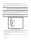
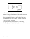
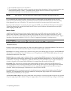
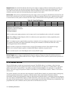
GP-IB Connection
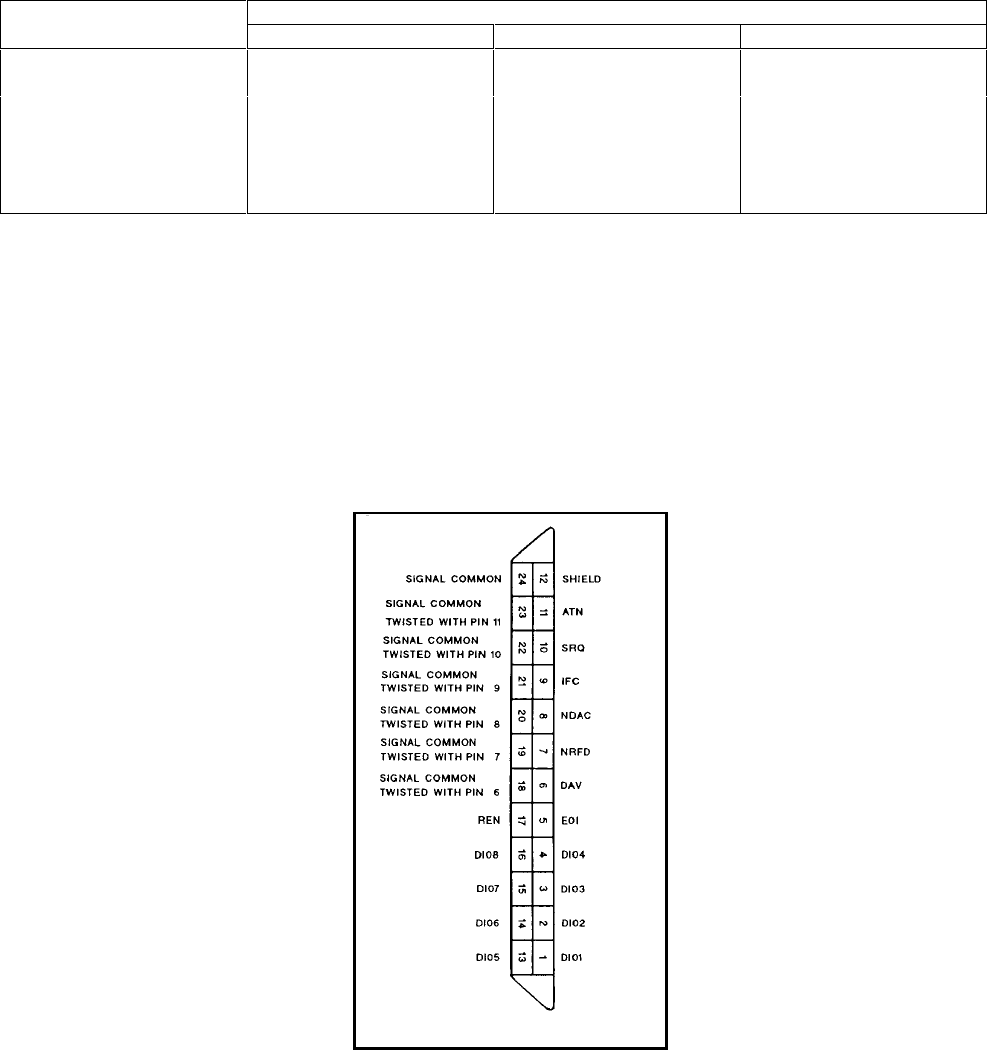
Connections between the power supply and the GP-IB are made via the GP-IB connector on the rear panel. Figure 3-7
shows the signals at each of the GP-IB connector pins. The GP-IB connectors table in Section 1 lists cables and cable
accessories that are available from Agilent. The GP-IB connector uses metric threads.
Figure 3-7. GP-IB Connector
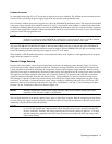
An GP-IB system may be connected together in any configuration (star, linear or combination) as long as the following rules
are followed: