


Operating Instructions
39
Foldback Protection
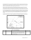
In some applications either CV or CC mode may be regarded as an error condition. The foldback protection feature protects
sensitive loads by disabling the power supply output if the unit switches to the prohibited mode.
In local control, foldback protection is toggled on or off by the FOLDBACK pushbutton switch. The output will be disabled
if the power supply switches from whichever mode (CV or CC) is in operation when foldback is enabled to the other mode.
In addition to turning foldback protection on and off, the FOLDBACK pushbutton switch also resets the foldback protection
circuit if it has tripped. The conditions which caused foldback should be corrected before the circuit is reset, or the foldback
protection circuit will trip again after reset.
NOTE If the foldback protection circuit has tripped and you want both to reset the circuit and disable foldback
protection, you must press the FOLDBACK switch twice in rapid succession, once to reset the foldback
protection circuit and the second time to turn off foldback protection before it trips again.
The green FOLDBACK ENABLED LED lights to indicate that foldback protection is enabled; the yellow FOLDBACK
LED lights to indicate that the foldback protection circuit has tripped. Note the ERROR LED will light if an attempt is made
to turn on foldback protection while the power supply is not in CV or CC mode.
When enabled via GP-IB foldback protection can be enabled for either mode, regardless of the operating state of the power
supply when the command is received.
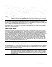
Remote Voltage Sensing
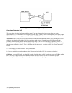
Because of the unavoidable voltage drop developed in the load leads, the strapping pattern shown in Figure 3-4 will not
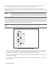
provide the best possible voltage regulation at the load. The remote sensing connections shown in Figure 3-6 improve the
voltage regulation at the load by monitoring the voltage there instead of at the supply’s output terminals. Remote sensing
allows the power supply to automatically increase the output voltage and compensate for the voltage drops in the load leads.
This improves the voltage regulation at the load, and is especially useful for CV operation with loads that vary and have
significant load-lead resistance. Note that with remote sensing, voltage readback is at the load. Remote sensing has no
effect during CC operation. When using remote sensing, turn off the power supply before changing the rear-panel straps,
sense leads, or load leads. Connect the unit for remote voltage sensing by connecting load leads from + OUT and - OUT
terminals to the load, disconnecting straps between + Out and + S and between - Out and - S, and connecting sense leads
from the + S and - S terminals to the load as shown in Figure 3-6.
NOTE Sensing is independent of other power supply functions; either local or remote sensing can be used
regardless of how the power supply is programmed.
The load leads should be of the heaviest practical wire gauge, at least heavy enough to limit the voltage drop m each lead to
0.5 volts. The power supply has been designed to minimize the effects of long load-lead inductance, but best results will be
obtained by using the shortest load leads practical.
NOTE Remote voltage sensing compensates for a voltage drop of up to 0.5 V in each lead, and there may be up
to a 0.12 V drop between the -output terminal and the internal sensing resistor, at which point the OVP
circuit is connected. Therefore, the voltage sensed by the OVP circuit could be as much as 1.12 V more
than the voltage being regulated at the load. It may be necessary to readjust the OVP trip voltage when
using remote sensing.