


Operating Instructions
46
Remote/Local. The remote/local function allows the power supply to operate in either local (front panel) or remote (via
GP-IB) control. The user can send Local Lockout to the power supply via GP-IB to disable the front-panel LCL switch
only. With Local Lockout, the controller determines if the unit operates in local or remote control; this enables the
controller to prevent anyone else from returning the power supply to local control.
Device Clear. Device Clear is implemented in the power supply as Clear (see Page 63). The difference between Clear and
Device Clear is that Device Clear can be an unaddressed or addressed command. Device Clear is typically used in systems
to send all devices in the system to a known state with a single command (which could be generated by a "panic" button).
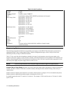
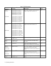
Table 3-5. Serial Poll Register
Bit Position 7 6543210
Bit Weight1286432168421
Condition - RQS ERR RDY - - PON FAU
RQS Requesting Service
ERR Remote Programming Error
RDY Ready to Process Commands
PON Power On Reset
FAU Fault Condition
RQS is set when power supply generates a service request, and is reset immediately after a serial poll is conducted.
ERR follows ERR bit in Status Register, which is set whenever power supply detects a remote programming error.
ERR is reset by ERR? query.
RDY is set whenever power supply finishes processing a command, and is reset when power supply starts to process a
new command. Note that power supply input buffer can accept new commands via GP-IB even while unit is busy
processing previously received commands.
PON is set when ac input power is turned on and is reset by CLR command or Device Clear interface message.
PON is set in serial poll register regardless of whether PON SRQ is enabled by rear-panel switch.
FAU is set when any bit is set in Fault Register and is reset by FAULT? query.
Device Trigger. Device Trigger is implemented in the power supply as Trigger (see Page 59). Each device that is to
respond to Device Trigger must be addressed. Device Trigger is typically used in systems to synchronize the operation of a
number of addressed devices.
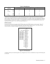
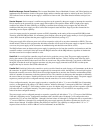
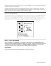
GP-IB Address Selection
The five GP-IB address switches are located on the rear panel. The GP-IB address is set in binary, with A1 the least
significant bit and A5 the most significant bit. Figure 3-8 shows the factory-set address of "5" (binary 00101). The raised
portion of the switch is shown in black. Any address from 00 to 30 decimal (00000 to 11110 binary) is a valid GP-IB
address. The power supply will operate on whatever valid address is set on the address switches. Address 31 will cause a
self-test error.
The operator should be aware that some other instruments on the GP-IB may initialize at a particular address although they
can be programmed subsequently to respond to a different address. If the system includes instruments with this
characteristic and they are programmed for addresses other than their initialized address, a momentary input power dropout
may cause them to re-initialize their address. If another instrument, such as the power supply, is hardware set to that address,
the system will not function properly. Therefore, the system program should be written to monitor any re-initialization. Any
programmed data, such as addresses, that may have been lost will then have to be reset.