


Installation
27
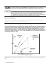
AC Line Impedance Check
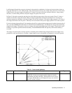
The power supply is designed for proper operation with line impedance typically found in ac power lines. However, if the
supply is connected to an ac power line having high impedance combined with line voltage near the minimum specified
value, (e.g., 104 Vac for nominal 120 Vac), the unit will go out of regulation if it is asked to provide full rated output power.
Such a situation might occur if the supply is connected to ac power an extended distance from the main ac distribution
terminals and/or if the ac power wires from the main ac distribution terminals are of relatively small gauge.
Measurement of ac line voltage at the supply input terminals typically is not a reliable indication of the actual ac line voltage
because of the peak clipping effect of the power supply and the averaging effect of the voltmeter. Symptoms of excessive
line impedance may include erratic or no output from the supply and/or inability of the supply to provide full output power.
If there is reason to suspect the ac power lines to the supply may have high impedance, perform the following check:
This check should be performed only by service-trained personnel who are aware of the hazards
involved (for example, fire and electrical shock). Turn power supply off before making or breaking
connections to power supply. Hazardous voltages are present within the unit even when power switch
is turned off.
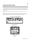
a. Connect a variable load to the supply. Using the OUTPUT ADJUST controls and DISPLAY SETTINGS, set voltage
and current (see Section III for detailed description) to maximum rating.
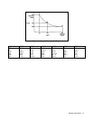
b. Set the load to the maximum rated output current for the power supply (see Table 1-1). The power supply output
voltage should be greater than:
65 V for Agilent 6030A 6 V for Agilent 6033A
8 V for Agilent 6031A 220 V for Agilent 6035A
22 V for Agilent 6032A 20 V for Agilent 6038A
c. If the supply voltage is less than specified, perform the power limit calibration given in the Service Manual. If the
power limit is calibrated correctly, but the unit still does not provide the required output, then the power supply is not
receiving adequate ac line input.
Repackaging For Shipment
To insure safe shipment of the instrument, it is recommended that the package designed for the instrument be used. The
original packaging material is reusable. If it is not available, contact your local Agilent Technologies Sales and Support
office to obtain the materials. This office will also furnish the address of the nearest service office to which the instrument
can be shipped. Be sure to attach a tag to the instrument specifying the owner, model number, full serial number, and service
required or a brief description of the trouble.
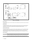
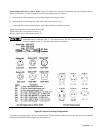
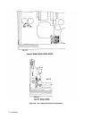
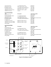
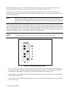
Rear Panel Screw Sizes and Part Numbers
Refer to the following list if you need to replace any of the rear panel connection hardware. Figure 2-4 identifies the part
number location.
Agilent Models 6030A, 6031A, 6032A, 6035A
Item Description Agilent Part number
ac input cover 5060-3237
ac input cover screws M4 X 0.7 X 60 mm (qty 4) 0515-0156
ac input barrier block 3-terminal barrier block 0360-2217
ac input barrier block screws 8-32 X 5/16 (qty 3) included with ac input barrier block
dc output cover 5040-1626
dc output cover screws M4 X 0.7 X 10 mm (qty 3) 0515-0414 (washer 3050-1053)
control signal barrier block 6 - terminal barrier block 0360-2195