


Operating Instructions
42
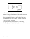
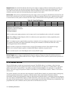
1. The total number of devices is no more than 15.
2. The total length of all the cables used is no more than two meters times the number of devices connected together, up to
an absolute maximum of 20 meters. (The length between adjacent devices is not critical as long as the total
accumulated cable length is no more than the maximum allowed.)
NOTE IEEE Std 488.1-1987 states that caution should be taken if individual cable length exceeds 4m.
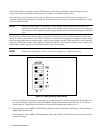
It is recommended that no more than three connector blocks be stacked together, as the resultant leverage can exert
excessive force on the mounting panels. Be certain that all connectors are full seated and that the lock screws are firmly
finger tightened. Do not use a screwdriver. The screwdriver slots in the lock screws are provided for removal only.
Page 44 provides information for operating the power supply in a GP-IB system. The Tutorial Description of the Agilent
Technologies Interface Bus and other documents listed in Section 1 provide additional information that may be helpful
when designing a GP-IB system.
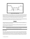
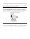
Monitor Signals
Amplified and buffered voltage and current monitor output signals are available at the rear-panel terminal strip. These
signals can be connected to remote meters to indicate output voltage and current. The signals vary from 0 to 5 volts to
indicate a zero to full-scale output. Both monitor-output terminals are referenced to the monitor-common terminal. Output
impedance of the monitor terminals is 10.2 k
±
5%; a load of 1 megohm will maintain 1% reading accuracy.
The common terminal ( M) is internally connected to the minus (-) output terminal.
Protective Circuits
Protective circuits within the power supply may limit or turn off the output in case of abnormal conditions. The cause of the
protective action can be determined by observing the front panel indicators (lights and meters).
Overrange. If an overrange condition exists (load tries to draw more power than the supply can deliver), the OVERRANGE
indicator turns on and both the CV and CC indicators are off. The product of the VOLTS and AMPS displays will exceed
the maximum output power of the supply.
Disabled. If the power supply output is disabled, either by a command from GP-IB, by protective circuits within the supply,
or by the INH input, the power supply output drops to zero and the DISABLED indicator turns on. The power supply can
be disabled by overvoltage, overtemperature, or foldback (indicated by front-panel LEDs), by low or high ac line (mains)
voltage, or externally via the remote inhibit (INH) input, by command from the controller (see Page 58).
Overvoltage. If the voltage across the power supply output terminals rises above a preset level, possibly because of a
hardware malfunction, the overvoltage protection (OVP) circuit will trip. If this occurs, the power supply will be disabled
and the OV indicator turned on. To reset the OVP circuit, first ensure that the condition that caused the overvoltage is
corrected. Then turn the power supply off and back on. or reset OVP via the GP-IB.
Overtemperature. If the overtemperature protection circuit trips, the power supply will be disabled and the OT indicator
turned on. The overtemperature circuit will reset automatically and the power supply output will be restored when the
temperature drops sufficiently for safe operation.
AC Line Over/Under Voltage. If the ac line (mains) input voltage increases or decreases beyond the range for safe operation
the power supply output may be disabled. The power supply output will be restored when the input voltage is within range.