


Operating Instructions
44
Constant Current Operation
To set up the power supply for constant current operation:
a. With power supply turned off, connect load to output terminals.
b. Turn on power supply. Hold in DISPLAY OVP pushbutton switch and set OVP ADJUST potentiometer for desired
OVP trip voltage. In CC mode the voltage setting will limit output voltage under quiescent conditions, and the OVP
circuit provides added protection against hardware faults.
c. Press OUTPUT ADJUST pushbutton switch once so that VOLTAGE indicator turns on, hold DISPLAY SETTINGS
pushbutton switch in, and rotate OUTPUT ADJUST knob to set desired voltage limit.
d. Press OUTPUT ADJUST switch once so that OUTPUT ADJUST knob controls current, and adjust output current to
desired level.
e. If foldback protection is desired, press FOLDBACK pushbutton switch to enable this feature.
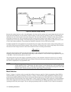
f. If a load change causes the voltage limit to be exceeded, the power supply automatically crosses over to constant
voltage operation and the output current drops proportionately. If foldback protection is enabled, mode crossover
causes the power supply output to be disabled. In setting the voltage limit, make adequate allowance for voltage peaks
that could cause unwanted mode crossover.
Return to Local
If the power supply is under remote control (RMT indicator on) and local lockout has not been sent (see Page 46), pressing
the LCL pushbutton switch will return the unit to local (front panel) control. Holding the LCL switch in will prevent the
power supply from returning to remote control for as long as the LCL switch is held in or until local lockout is sent.
If the power supply has been disabled via GP-IB, or remote inhibit (DISABLED indicator on), the LCL switch will not
restore the output. The only way to re-enable locally is to turn the LINE switch off and then back on. The OUTPUT
ADJUST controls continue to operate in local control even if the power supply is disabled.
NOTE Once the soft limits have been set by the controller via GP-IB, the OUTPUT ADJUST knob cannot be
used to obtain a higher output beyond these limits. This condition is true for both local and GP-IB control.
GP-IB Operation
Interface Functions
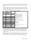
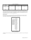
The power supply implements the following GP-IB interface functions, which are defined by IEEE standard 488:
SH1 (Source Handshake)
AH1 (Acceptor Handshake)
T6 (Talker)
L4 (Listener)
SR1 (Service Request)
RL1 (Remote Local)
PP1 (Parallel Poll)
DC1 (Device Clear)
DT1 (Device Trigger)