


Installation
23
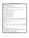
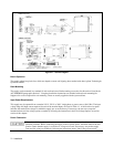
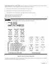
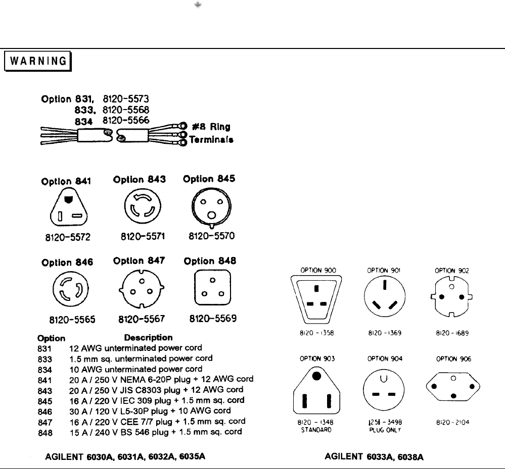
Agilent Models 6033A, 6031A, 6032A, 6036A. Figure 2-2 illustrates the standard configuration of power-cord plugs used by
Agilent Technologies. To connect input power, to the instrument proceed as follows:
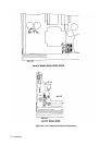
a. Remove the AC filter assembly cover by unscrewing the four locating screws.
b. Insert the power cord through the strain relief clamp located on the cover.
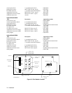
c. Connect the wires to the terminal block in accordance with the prevailing color codes.
Green or green/yellow to the terminal labeled "
’’
White or blue wire to the terminal labeled "N’’
Black or brown wire to the terminal labeled ’’L"
For proper protection by the instrument circuit breaker, the wire connected to the "L’’ terminal on the
instrument must be connected to the "L’’ side of the line (hot); the wire connected to the ’’N" terminal
must be connected to the "N" side of the line (neutral or common).
Figure 2-2. Power-Cord Plug Configurations
To protect operating personnel, the wire connected to the terminal must be connected to earth ground. In no event shall this
instrument be operated without adequate ground connection.