


Operating Instructions
72
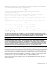
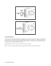
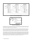
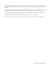
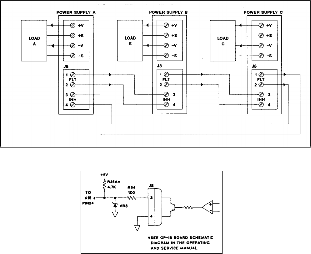
Figure 3-19a. FLT and INH with Multiple Supplies
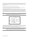
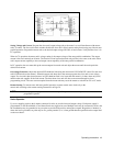
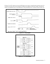
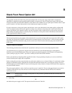
Figure 3-19b. Typical INH Setup
Closing the hood will not re-enable the supply, and during a serial poll the controller would be made aware that a fault exists
via the FAU bit in the serial poll register. The fault register must now be read to reset the FLT and RI bit. Finally sending
CLR will initialize the supply to its power on state (see Table 3-6).
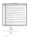
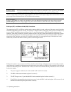
Figure 3-18 shows an example of how to physically isolate the output of the supply from the load. The FLT output will go
true for any unmasked fault condition (see Table 3-9), and it is used to trigger a relay driver circuit. When it is tripped, the
relay driver circuit energizes the relay and the supply is then disconnected from the load. The fault line can be reset by
reading the fault register and the power supply can be initialized to its power-on-state (see Table 3-6) by sending a CLR.
The setup in Figure 3-19a chains the FLT output of one supply to the INH input of the next. In this case a fault condition in
any of the supplies would cause all of the supplies to be disabled simultaneously without controller involvement or external
circuitry. The controller can be made aware of the fault via a service request (SRQ). Sending a FAULT? and then a RST
will restore the outputs of the supplies to their programmed values before the INH circuit was tripped. Sending a CLR will
initialize the supply to its power-on-state (see Table 3-6). To provide proper operation, correct polarity must be observed
when connecting external circuitry to the INH input. A typical example is shown in Figure 3-19b.