


Standard Commands for Programmable Instruments (SCPI)
104
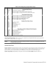
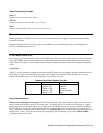
Query Syntax [SOURce]:VOLTage[:LEVel] [:IMMediate][:AMPLitude]?
[SOUR
ce]:VOLTage[:LEVel] [:IMMediate][:AMPLitude]? MAX
[SOUR
ce] :VOLTage[:LEVel] [:IMMediate] [:AMPLitude] ? MIN
[SOUR
ce]:VOLTage[LEVel]:TRIGger [:AMPLitude]?
[SOUR
ce]:VOLTage[LEVel]:TRIGger [:AMPLitude]? MAX
[SOUR
ce]:VOLTage[:LEVel]:TRIGger [:AMPLitude]? MIN
Returned Parameters <NR3> VOLT? and VOLT:TRIG?
return presently programmed voltage levels. If the
TRIG level is not programmed, both returned values are the same.
VOLT MAX? and VOLT MIN? return the maximum and minimum programmable
immediate voltage levels.
VOLT:TRIG? MAX and VOLT:TRIG? MIN return the maximum and minimum
programmable triggered voltage levels.
VOLT:PROT[:AMPL]?
Queries the overvoltage protection level of the power supply. The overvoltage protection level can only be set from the
front panel OVP potentiometer.
Query Syntax [SOURce]:VOLTage:PROTection [:AMPLitude]?
Returned Parameters <NR3> VOLT:PROT?
returns the presently set OVP level.
Examples VOLT: PROT? VOLTAGE: PROTECTION: AMPLITUDE?
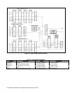
STATUS REPORTING
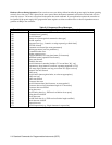
Figure C-4 shows the status structure of the power supply in SCPI mode. The Standard Event, Status Byte, Service Request
Enable registers and the Output Queue perform standard GP-IB functions defined in the
IEEE 488.2 Standard Digital
Interface for Programmable Instrumentation.
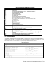
The Operation and Questionable Status registers implement the status reporting
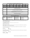
requirements of the power supply. Table C-5 shows the bit configuration of each status register.
Questionable Status Group
Register Functions.
The Questionable Status registers record signals that indicate abnormal operation of the power supply.
As shown in Figure C-4, the group consists of a Condition register, PTR/NTR Filter, Event register, and Enable register.
•
The condition register holds real-time status transitions from the circuit being monitored. It is a read-only register.
•
Each bit of the PTR filter, when programmed ON (1), allows a 0-to-1 transition of the corresponding Condition register
bit to set the corresponding bit of the Event register.
•
Each bit of the NTR filter, when programmed
On (1), allows a 1-to-0 transition of the corresponding Condition register
bit to set the corresponding bit of the Event register.
•
The Event register latches any condition that is passed through by the PTR or NTR filter. It is a read-only register
(STAT:QUES:EVEN?) that is cleared when read.
• The Enable register serves as a mask between the Event register and the Logical OR circuit that sets the QUES(tion) bit
(3) of the Status Byte register. If a bit in the Enable register is programmed
On (1), it allows the corresponding Event
register bit to be summed into the QUES bit. The register is a readlwrite register programmed with the
STAT:QUES:ENAB command.
Register Programming. Programming for this group is derived from the STAT:QUES commands (see Table C-2).