


Operating Instructions
66
The following paragraphs discuss in greater detail the methods of remotely programming the output voltage or current using
either a resistance or voltage input. Whichever method is used, the wires connecting the programming device must be
shielded to reduce noise pickup. The outer shield of the cable should not be used as a conductor, and should be connected to
ground at one end only.
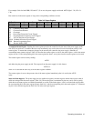
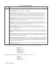
Refer to Table 3-4 for mode-switch settings for voltage or resistance programming.
Although the following setup drawings (Figure 3-9 through 3-13) show the supply strapped for local sensing, analog
programming and remote voltage sensing do not interact and may be used simultaneously.
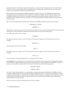
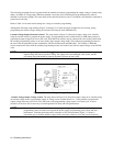
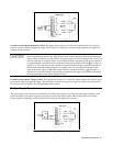
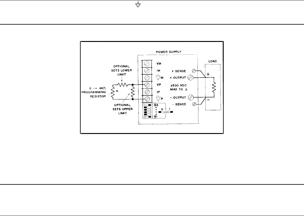
Constant Voltage Output, Resistance Control. The setup shown in Figure 3-9 allows the output voltage to be varied by
using an external resistor to program the power supply. A programming resistor variable from 0 to 4000 ohms produces a
proportional output voltage from zero to full scale. Note that fixed resistors may be connected in series and/or parallel with
the variable programming resistor to set lower and/or upper output voltage limits. The resultant programming resistance is
the sum of the series/parallel resistor combination, and must be between 0 and 4000 ohms. For example, a 2000 ohm
resistor connected in series with the variable programming resistor will set the lower limit for output voltage at one-half full
scale.
NOTE If the programming terminals (VP to P) become open circuited during resistance programming, the
output voltage will tend to rise above rating. The supply will not be damaged if this occurs, but the
overvoltage trip point should be properly adjusted to protect the user’s load.
Figure 3-9. Resistance Programming of Output Voltage
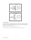
Constant Voltage Output, Voltage Control. The setup shown in Figure 3-10 allows the output voltage to be varied by using
an external voltage source to program the supply. A voltage source variable from 0 to + 5 volts produces a proportional
output voltage from zero to full scale. The static load on the programming voltage source is less than 5
µ
A. A source
resistance of less than 10 k is necessary to avoid degradation of offset and drift specifications.
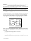
NOTE If external resistors are used to limit the remote-programming voltage to 5 Vdc, the resulting high
programming-source resistance can degrade the power supply’s programming speed, offset and drift
performance. Limit the equivalent source resistance to 10 k ohm maximum. Figure 3-11 shows a
convenient way to calculate suitable voltage-divider resistance values for a 5 k ohm source resistance.