


Operating Instructions
38
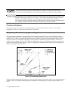
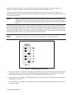
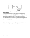
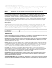
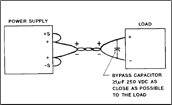
Figure 3-5. Connecting a Bypass Capacitor
Overvoltage Protection (OVP)
The overvoltage trip point is adjusted at the front panel. The approximate trip voltage range is from zero volts to
approximately 107% of maximum rated voltage of the power supply. When the OVP circuit trips, the power supply output
is disabled and delivers no output power, and the OVP and DISABLED indicators turn on.
Adjustment. OVP is set by the recessed single-turn OVP ADJUST potentiometer on the front panel. Rotating the control
clockwise sets the trip voltage higher. (It is set to maximum at the factory.) When adjusting the OVP trip point, the
possibility of false tripping must be considered. If the trip voltage is set too close to the supply’s operating voltage, a
transient in the output would falsely trip the OVP. For this reason it is recommended that the OVP trip voltage be set higher
than the output voltage by at least 1 volt (see NOTE on the following page). To adjust the OVP trip voltage, proceed as
follows:
a. Turn on supply and hold DISPLAY OVP pushbutton in.
b. Insert a small-blade screwdriver through hole in front panel and adjust OVP trip voltage to desired level.
OVP Reset. To reset OVP locally, turn the LINE switch off and then back on. OVP can also be reset via GP-IB by sending
RST. The cause of the overvoltage must be removed before the OVP circuit is reset or the circuit will trip again
immediately. If the OVP circuit trips continuously check the load and the trip voltage.