


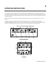

Operating Instructions
37
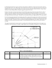
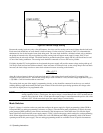
If multiple loads are connected to one supply, each load should be connected to the supply’s output terminals using separate
pairs of connecting wires. This minimizes mutual coupling effects and takes full advantage of the supply’s low output
impedance. Each pair of connecting wires should be as short as possible and twisted or shielded to reduce noise pickup and
radiation.
If load considerations require the use of output distribution terminals that are located remotely from the supply, then the
power supply output terminals should be connected to the remote distribution terminals by a pair of twisted or shielded
wires and each load should be separately connected to the remote distribution terminals. Remote voltage sensing is required
under these circumstances (page 39). Sense either at the remote distribution terminals, or (if one load is more sensitive than
the others) directly at the most critical load.
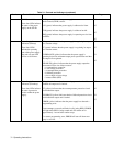
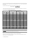
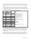
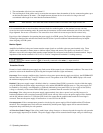
Table 3-3. Stranded Copper Wire Ampacity
Wire Size
AWG Cross Section
Area in mm
2
Ampacity NOTES:
22 5.0 1. Ratings for AWG-sized wires are
20
18
0,75
8.33
10
15.4
derived from MIL-W-5088B.
Ratings for metric-sized wires are
derived from IEC Publication 335-1.
1 13.5 2. Ampacity of aluminum wire is
16 19.4 approximately 84% of that listed
1.5 16 for copper wire.
4 31.2 3. When two or more wires are bundled
2.5 25 together, ampacity for each wire
12 40 must be reduced to the following percentages:
4 32 2 conductors 94%
10 55 3 conductors 89%
6 40 4 conductors 83%
8 75 5 conductors 76%
10 63
6 100
4. Maximum temperatures: Ambient, 50
°
C;
4 135
Conductor, 105
°
C
2 180
0 245
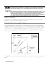
Either positive or negative voltages can be obtained from the supply by grounding one of the output terminals. It is best to
avoid grounding the output at any point other than the power supply output terminals to avoid noise problems caused by
common-mode current flowing through the load leads to ground. Always use two wires to connect the load to the supply
regardless of where or how the system is grounded. Never ground the system at more than one point. The maximum
potential (including output voltage) that either output terminal is from ground must not exceed that specified on the output
label on the rear chassis.
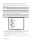
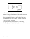
The PARD specifications in Table 1-1 apply at the power supply output terminals. However, noise spikes induced in the
load leads at or near the load may affect the load although the spikes are inductively isolated from the power supply. To
minimize voltage spikes at the load, connect a bypass capacitor as shown in Figure 3-5. With this setup, peak-to-peak noise
at the load can actually be reduced to a level well below the value specified at the power supply output terminals.